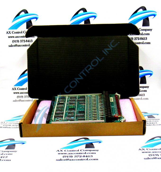
About the DS3800HSCD1G1E
The GE High Level Non-Isolated Input Board DS3800HSCD1G1E features a modular connector on 1 end and retention levers on the other end. The board is populated with a multiple capacitors. The board is populated with multiple transistor-transistor logic devices. The GE High Level Non-Isolated Input Board DS3800HSCD1G1E is also populated with 16 red indicator LEDs and 1 amber indicator LED. The board also has 1 socket for electrically erasable programmable read-only memory (EEPROM) modules. The board is also populated with 3 trimmer resistors.
The GE High Level Non-Isolated Input Board DS3800HSCD1G1E is not populated with connectors for ribbon cables or other types of cable connectors. All current and control signals are carried by the modular connector. The modular connector is located opposite from the retention levers. A matching modular connector is located in the board rack. When the 2 modular connectors meet, they connect to enable the current and control signal connections. The retention levers produce a cam action that presses the retention levers together and secures the connection.
To install the board, slide the board into the rack and make sure it doesn’t scrape against other boards or components when you insert it. When the board is inserted in the rack and the retention levers engage the retention mechanism, press down on the levers to lock the board in the rack. At the same time, the modular connectors mate and the control signals and current connections are made. The control signals are transmitted to the board. They are also transmitted from the GE High Level Non-Isolated Input Board DS3800HSCD1G1E.


