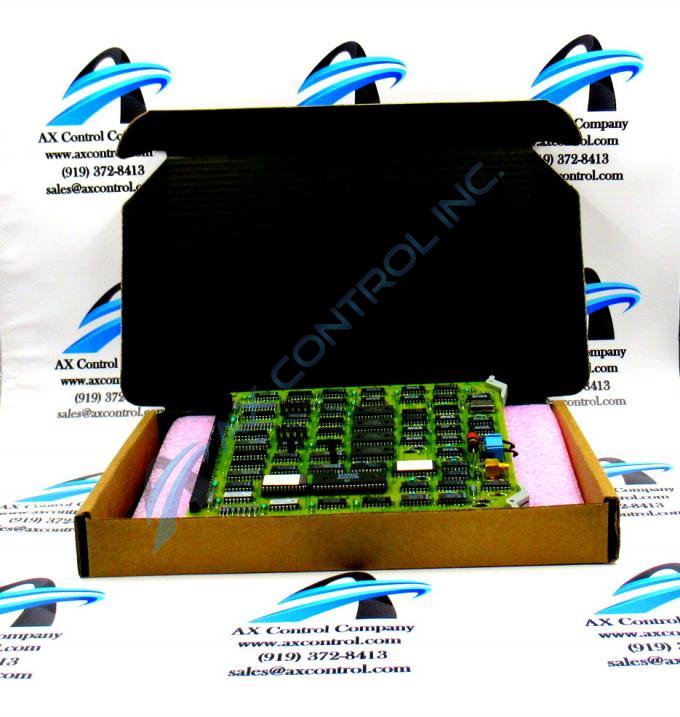
About the DS3800HVDB
The GE Video Driver Board DS3800HVDB is designed for quick installation in the drive. The board features a modular connector on 1 end and retention levers on the other end. The GE Video Driver Board DS3800HVDB also is populated with 1 20-pin connector between the retention levers. The board is also populated with multiple erasable programmable read-only memory (EPROM) modules and 15 jumpers.
The 20-pin connector on the GE Video Driver Board DS3800HVDB is designed for an operator to connect a ribbon cable after the board is installed in a drive. If connected after the board is installed, there is a reduced risk of placing strain on the ribbon cable. Stress can cause the fine wires in each of the 20 strands to pull out. This would result in the signal connection being lost. If the cable is connected before installing the board, you might accidentally tug the ribbon cable and damage the connections. The 20-pin connector is equipped with retention latches. The retention latches swing over the connector and prevent it from being removed.
The latch is secured with a tab when it is installed. To remove the latch, move the latch off the tab and swing it over the connector. Then, grasp the connector and pull it out of the connector on the board. To install a 20-pin connector, align the ribbon cable and firmly insert it into the board connector. Close the latch over the ribbon cable until it snaps into place.


