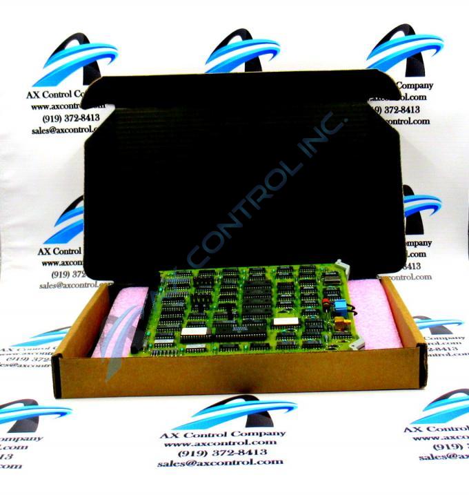
About the DS3800HVDB1H1F
The GE Video Driver Board DS3800HVDB1H1F is designed for quick installation in the drive. The board features a modular connector on 1 end and retention levers on the other end. The GE Video Driver Board DS3800HVDB1H1F also is populated with 1 20-pin connector between the retention levers. The board is also populated with multiple erasable programmable read-only memory (EPROM) modules and 15 jumpers.
Hardware Tips and Specifications
The 20-pin connector on the board is provided with retention latches. It is located between the retention levers that secure the GE Video Driver Board DS3800HVDB1H1F. The latches use a cam action against the board rack to secure the board. That is, the board is pressed into the modular connector at the rear of the board rack. The modular connector located on the board fits into the modular connector on the rack. This modular connection secures the control signals. The board receives some of the signal for processing. The board also transmits new signals after processing. Also carried over the modular connection is the voltage used to power the board.
When you remove the board from the rack, lift up on the retention levers to release the board from the rack. You will find it necessary to use 2 hands to lift the board out of the rack. Place your hands on the side of the boards and do not press against any of the components. Place it on a clean, dry, and sturdy surface. This might be a desktop or workbench. This DS3800HVDB1H1F Video Driver CD device has a group one Mark IV Series grouping, about the most common across the entire legacy series stored here.


