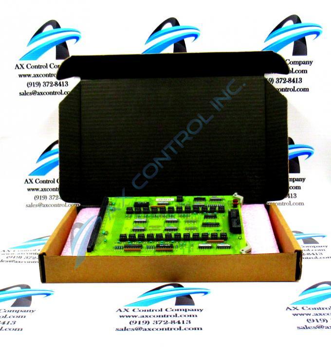
About the DS3800HXTA1E1E
The DS3800HXTA1E1E printed circuit board was developed as a Series 6 transmitter to fit into the Mark IV (Speedtronic) turbine control series. The Mark IV is a gas and steam turbine control system. It has been created with integrated chipsets utilizing triple-redundant sixteen-bit microprocessors. By using the theory of controlled failure--where electronics failures are expected to happen from time to time and are planned for, thus circumvented by in-place fail safes--the Speedtronic system keeps the turbines up and running.
Hardware Tips and Specifications
The DS3800HXTA1E1E is built with 40 integrated circuits. This includes quad differential receivers and line drivers. Many of these circuits meet or exceed the requirements of ANSI TIA/EIA-422-B. The DS3800HXTA1E1E has five resistor network arrays. These are placed parallel to the long sides of the board. Resistor arrays may be used for voltage division or could be a terminal for SDRAM or DDRAM. The working voltage (max) of five resistor arrays is 25V. The DS3800HXTA1E1E has one test point, marked 'dcom.' This is located near its two LEDs, which are marked 'parity ok' and 'chain ok.' The DS3800HXTA1E1E also has 8 pairs of plated through holes (PTH) near the center of the board in case extra components need to be added. The board has been drilled at the factory in all four corners.
The DS3800HXTA1E1E has two connectors designed for communication with other PCBs. One is male (218A4637-P6) and one female. These are located opposite each other on the short ends of the boards. Installation guidelines may be found within the data sheet or manual from the original manufacturer for the DS3800HXTA1E1E. Technical support for this product was originally provided by GE.


