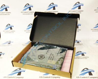
About the DS3800NEPB1G1F
The GE Power Excitation Board DS3800NEPB1G1F can only operate when installed in a power control module. The board must be connected to a motor excitation board. Connector JR on the DS3800NEPB1G1F board provides the signals for the tach voltage at a maximum of 300 volts and also the field reference from the terminal board to the motor excitation board.
Connector JT on the DS3800NEPB1G1F board supplies the input for the amature shunt lead at 150mv and the positive armature volts at 750 volts. It also supplies the negative armature volts at 750 volts.
The control panel on the power conversion module enables the operator to control the operation of the board and can also view the status of the module. LED indicators display the control mode that the device is using. The control modes are available to the operator are Start Up, Acceleration, Speed Horsepower, and Temperature. LED indicators also show the Control Sequence. The control sequences are Check, Ready, Start, Sequence In Progress, Flame 1, Flame 2, Idle, and Comp Sequence. The operator can also Start or Stop the Master Control.
When you install the board in the power conversion module, you must follow specific guidelines to keep the DS3800NEPB1G1F from damage. Never apply pressure to the top surface of the board. The components are delicate and prone to damage. You might break off the component or damage the jumper and connector pins. You might also accidentally remove a jumper or damage other components.


