About the DS3800NEPD1H1D
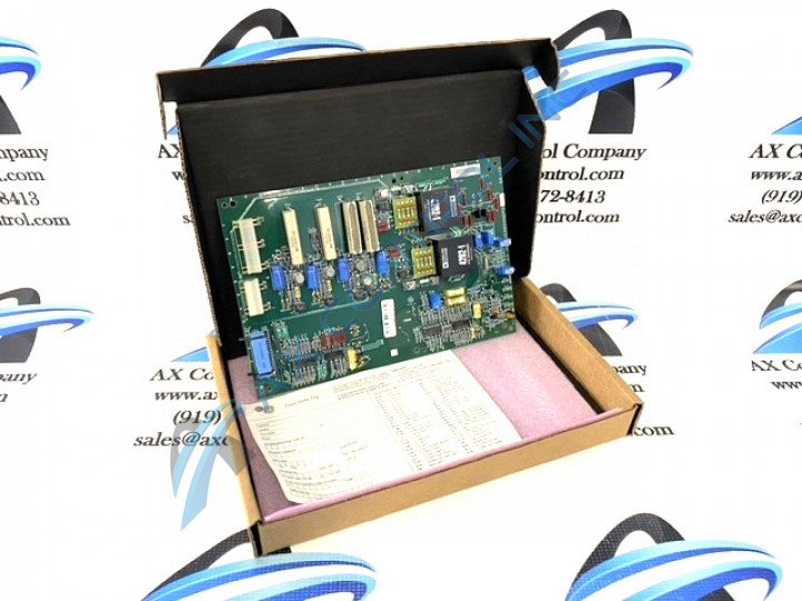
The GE Excitation Power Board DS3800NEPD1H1D features a hole in each corner through which you can insert a screw to secure the board. The board is populated with multiple capacitors. The board is populated with 2 Analog Devices power components. The GE Excitation Power Board DS3800NEPD1H1D is also populated with 1 amber indicator LED. The board also has 1 34-pin connector and multiple wire terminals for attaching wires and components to circuits. The board is also populated with 5 trimmer resistors.
The wire terminals on the GE Excitation Power Board DS3800NEPD1H1D are specifically designed to support the installation of additional resistors. The board has 4 wire terminals and they are located in pairs. A servicer can install an additional resistor between a pair of wire terminals. The ID of 1 additional resistor is ARM and the ID of the other is FLD. An engineer or servicer determines the need for an additional resistor based on the function of the board.
If the resistor must be installed, remove the board from the drive and place it on a clean surface. Wear a wrist strap or other device that drains static electricity from the body and the board. Use a screwdriver to loosen the screw on top of the wire terminal. However, do not remove the screw. Insert the resistor lead wire into the terminal and tighten it. Repeat the action for the other terminal. Cut off any excess lead wire to prevent a short circuit. Use 2 hands to place the board back into the drive and install the 4 screws. Reconnect any ribbon cables or other cables.


