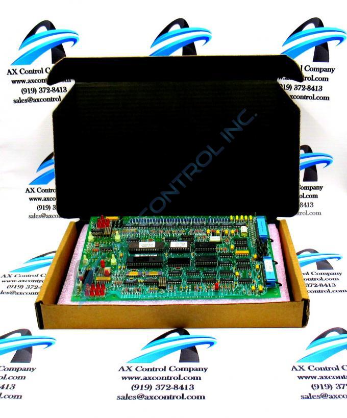
About the DS3800NFCD
The GE Firing Circuit Board DS3800NFCD features 1 hole in each corner for attaching the board to the drive interior with screws. The board is populated with 4 standoffs for attaching a daughter card. The daughter card provides additional processing, connectors, and features. The board is populated with multiple transistor-transistor logic devices. The GE Firing Circuit Board DS3800NFCD is also populated with 13 red indicator LEDs and 1 amber indicator LED. The board also has 1 socket for electrically erasable programmable read-only memory (EEPROM) modules. The board is also populated with multiple jumpers and 2 34-pin connectors.
The daughter card is populated with 4 jumpers and 3 potentiometers with a dial control. It also has multiple signal cable pin connectors. The potentiometers have IDs associated with them. 1 ID is AMMETER, 1 is 12 VOLT FB, and the last potentiometer is LOGIC CL. Only a qualified technician can adjust the potentiometers because a calibrated testing device is needed as well as the training to work with high-voltage devices. Turn the dial to adjust the potentiometer while the testing device registers the electric current. When the proper current is achieved, the task is complete.
The jumpers on the daughter card have IDs silkscreened on the surface of the card. The prefix is J and the suffix is F. The second character is a number. For example J5F, J6F, and J7F are some of the IDs.
The daughter card is secured on the GE Firing Circuit Board DS3800NFCD with use of the standoffs. The standoffs align with the 1 hole in each corner of the daughter card.


