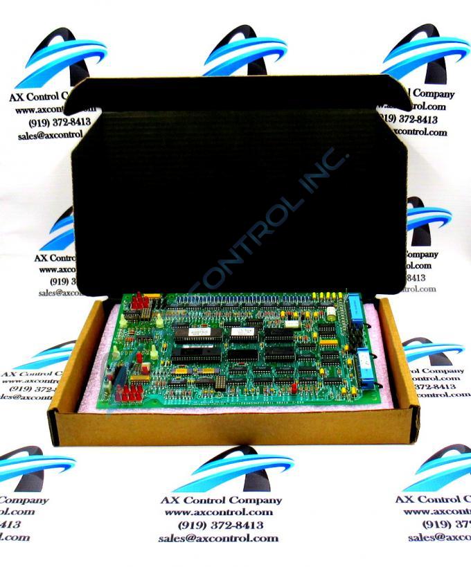
About the DS3800NFCD1G1H
The GE Firing Circuit Board DS3800NFCD1G1H features 1 hole in each corner for attaching with screws the board to the drive interior. The board is populated with 4 standoffs for attaching a daughter card. The daughter card provides additional processing, connectors, and features. The board is populated with multiple transistor-transistor logic devices. The GE Firing Circuit Board DS3800NFCD1G1H is also populated with 13 red indicator LEDs and 1 amber indicator LED. The board also has 1 socket for electrically erasable programmable read-only memory (EEPROM) modules. The board is also populated with multiple jumpers and 2 34-pin connectors.
The red LEDs are divided into 2 groups on the GE Firing Circuit Board DS3800NFCD1G1H. 1 group is comprised of 7 red LEDs. The other group is comprised of 7 red LEDs and also 1 amber LED. The LEDs indicate the health of the board and the status of processing on the separate circuits.
The 2 34-pin connectors are situated so that the cable plugs into the connectors from the side of the board. This improves the usability of the connectors because the user can access the cables while the board is installed in the drive.
The GE Firing Circuit Board DS3800NFCD1G1H is designed to accommodate several different daughter cards. The board is populated with 3 connectors into which a daughter card be connected. It also has holes into which standoffs can be inserted. The daughter card option you choose depends on the additional functionality needed for the drive. First the technician installs the standoffs into the appropriate holes on the board.Then, press the card into the standoffs and into the connector.


