About the DS3800NFCD1H1D
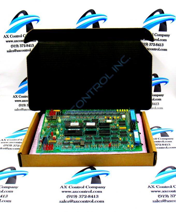
The GE Firing Circuit Board DS3800NFCD1H1D features 1 hole in each corner for attaching with screws the board to the drive interior. The board is populated with 4 standoffs for attaching a daughter card. The daughter card provides additional processing, connectors, and features.
Hardware Tips and Specifications
The board is populated with multiple transistor-transistor logic devices. The GE Firing Circuit Board DS3800NFCD1H1D is also populated with 13 red indicator LEDs and 1 amber indicator LED. The board also has 1 socket for electrically erasable programmable read-only memory (EEPROM) modules. The board is also populated with multiple jumpers and 2 34-pin connectors. The GE Firing Circuit Board DS3800NFCD1H1D is populated with 3 connectors for attaching daughter cards. It also is engineered with holes for inserting standoffs. The standoffs perform 2 functions.
The standoffs secure the daughter card in the connectors and on the board. The standoffs also keep the daughter cards off the surface of the board. That is, they keep the daughter card above the board which protects the board from damage. To install a daughter card, first locate the holes in the board that align with the holes in the daughter card. Insert the plastic standoffs into the holes. Then, align the daughter card over the standoffs and press the daughter card into the standoffs. Press on the daughter card gently until it clicks in place on the standoffs. One daughter card also is populated with a 10-pin ribbon cable. The 10-pin ribbon cable terminates with a 10-pin connector. Press it into the 10-pin connector on the board to enable additional control signals to pass to the daughter card.


