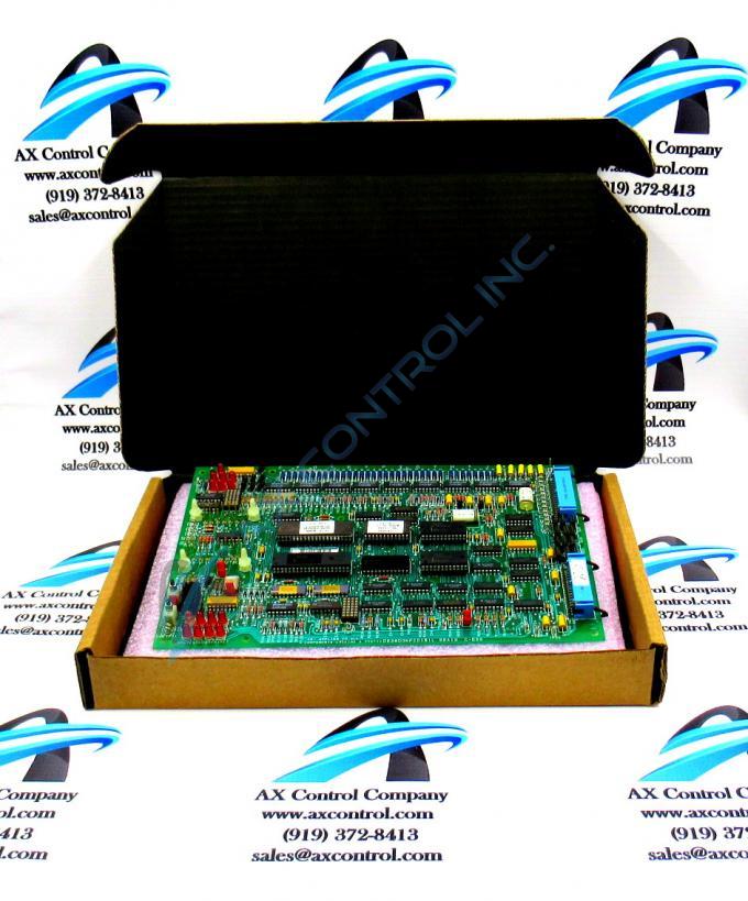
About the DS3800NFCD1J1C
The GE Firing Circuit Board DS3800NFCD1J1C features 1 hole in each corner for attaching with screws the board to the drive interior. The board is populated with 4 standoffs for attaching a daughter card. The daughter card provides additional processing, connectors, and features. The board is populated with multiple transistor-transistor logic devices. The GE Firing Circuit Board DS3800NFCD1J1C is also populated with 13 red indicator LEDs and 1 amber indicator LED. The board also has 1 socket for electrically erasable programmable read-only memory (EEPROM) modules. The board is also populated with multiple jumpers and 2 34-pin connectors.
Hardware Tips and Specifications
If you suspect that a problem exists with the GE Firing Circuit Board DS3800NFCD1J1C, troubleshooting tools are available to diagnose the problem. The board is populated with test points. The test points enable a qualified technician to test the circuits and components of the board. A qualified technician will have the tools and properly calibrated testing tools to perform the work. A service document is available that describe the allowable reading for each test point. If a reading is outside of the range, a problem might exist. The test points all have IDs that are prefixed with TP. The TP is followed by a number. TP21, TP22, and TP23 are some examples.
Another troubleshooting tool is the diagnostic tools on the GE Firing Circuit Board DS3800NFCD1J1C. The report is generated when you run the diagnostic tool. It gives a history of activity associated with the drive. It includes all errors and warnings and trip conditions. For example, a trip condition is triggered if the interior of the drive is too hot and reaches a predetermined threshold.


