About the DS3800NFCD1K1C
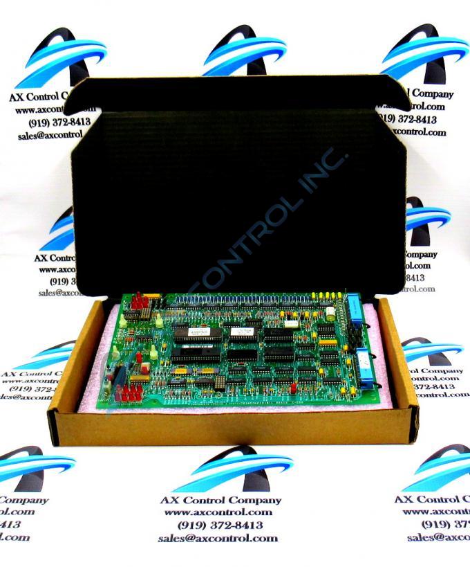
The GE Firing Circuit Board DS3800NFCD1K1C features 1 hole in each corner for attaching with screws the board to the drive interior. The board is populated with 4 standoffs for attaching a daughter card. The daughter card provides additional processing, connectors, and features. The board is populated with multiple transistor-transistor logic devices. The GE Firing Circuit Board DS3800NFCD1K1C is also populated with 13 red indicator LEDs and 1 amber indicator LED. The board also has 1 socket for electrically erasable programmable read-only memory (EEPROM) modules. The board is also populated with multiple jumpers and 2 34-pin connectors.
The 34-pin connectors are located on 1 edge of the board so that the ribbon cables will not interfere with the components on the board. That is, the ribbon cables can be routed away from the board and along the side of the drive and not across the surface of the board. The 34-pin connectors have retention latches that keep the ribbon cables from accidently disconnecting. However, the retention latches require some special consideration. Before you can connect a ribbon cable to the connector, you must swing aside the retention latches one at a time. Then, you can connect the ribbon cable to the connector on the board. To secure the ribbon cable, swing the retention latches over the ribbon cable until they snap into place.
When you remove a ribbon cable from the connector, first swing open the retention latches. Then, hold the ribbon cable by the plastic connector and gently pull it out of the connector on the board.


