About the DS3800NFCD1K1E
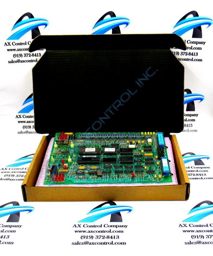
The GE Firing Circuit Board DS3800NFCD1K1E features 1 hole in each corner for attaching with screws the board to the drive interior. The board is populated with 4 standoffs for attaching a daughter card. The daughter card provides additional processing, connectors, and features. The board is populated with multiple transistor-transistor logic devices. The GE Firing Circuit Board DS3800NFCD1K1E is also populated with 13 red indicator LEDs and 1 amber indicator LED. The board also has 1 socket for electrically erasable programmable read-only memory (EEPROM) modules. The board is also populated with multiple jumpers and 2 34-pin connectors.
The GE Firing Circuit Board DS3800NFCD1K1E is populated with 3 female 28-pin connectors. The connectors are designed to connect to daughters cards that are installed above the board. The daughter cards have a matching connector on the back side. When you press the daughter card onto the board, the 28-pin connectors connect.
The 28-pin connectors carry the voltage that powers the card. The connectors also carry the control signals that are received by the card for processing. Other control signals are sent from the card to the board. 1 daughter card also is populated with a 10-pin ribbon cable. One end of the ribbon cable is permanently attached to the card and the other end terminates in a 10-pin connector. Plug the connector on the ribbon cable into the connector on the GE Firing Circuit Board DS3800NFCD1K1E. Only disconnect or connect the 10-pin ribbon cable when the board is disconnected from power and is removed from the drive.


