About the DS3800NFCD1L1D
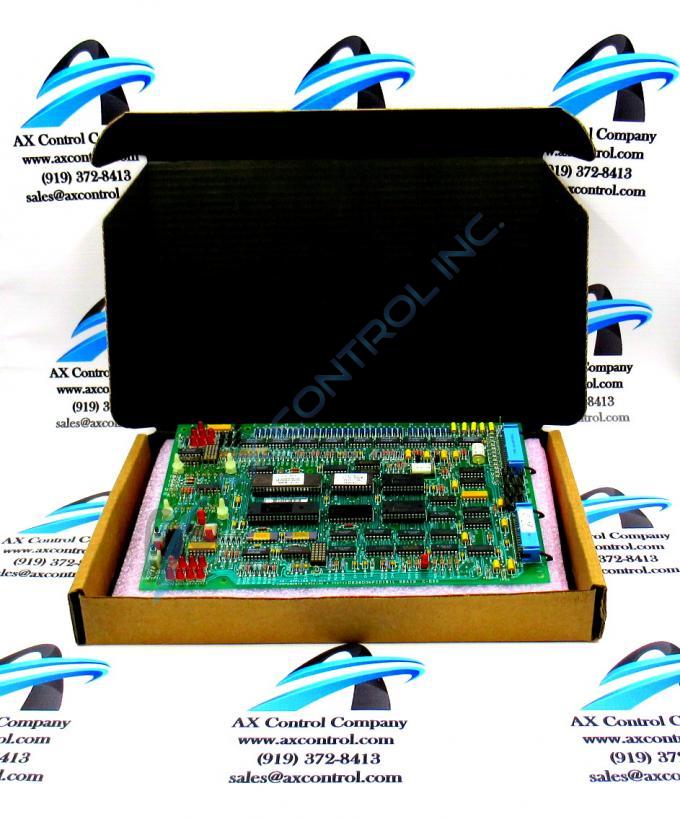
The GE Firing Circuit Board DS3800NFCD1L1D features 1 hole in each corner for attaching with screws the board to the drive interior. The board is populated with 4 standoffs for attaching a daughter card. This DS3800NFCD1L1D device here would be protected by a guat
Hardware Tips and Specifications
The daughter card provides additional processing, connectors, and features. The board is populated with multiple transistor-transistor logic devices. The GE Firing Circuit Board DS3800NFCD1L1D is also populated with 13 red indicator LEDs and 1 amber indicator LED. The board also has 1 socket for electrically erasable programmable read-only memory (EEPROM) modules. The board is also populated with multiple jumpers and 2 34-pin connectors. If you have installed a daughter card on the GE Firing Circuit Board DS3800NFCD1L1D, additional consideration must be given to the fact that the extra weight and bulk can make installation more difficult. When you insert the board into the drive use 2 hands to hold the board and have a good view of the drive interior so that you can avoid hitting the board or damaging other components in the drive.
When the board is installed and the drive is operating the technician and operators can view the indicator LEDs to monitor the operation of the drive. The LEDs have ID that are prefixed with CR. The prefix is followed by a number. Also printed on the board are descriptive labels that indicate the purpose of the LED. For example, LEC, 1 FLT, and TOL are some of the labels. If a problem occurs, the operator can run the diagnostic programs on the drive to determine the source of the problem.


