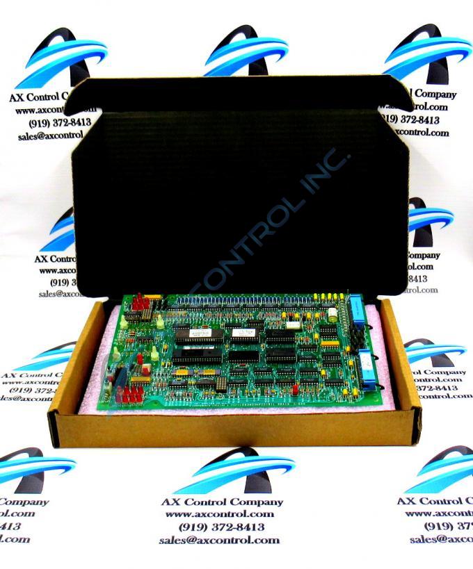
About the DS3800NFCD1N1E
The board is populated with 4 standoffs for attaching a daughter card. The daughter card provides additional processing, connectors, and features. The GE Firing Circuit Board DS3800NFCD1N1E additionally features:
- 1 hole in each corner
- multiple transistor-transistor logic devices
- 13 red indicator LEDs
- 1 amber indicator LED
- 1 socket for EEPROM modules
- multiple jumpers
- 2 34-pin connectors
DS3800NFCD1N1E Firing Circuit Board Diagnostics
The GE Firing Circuit Board DS3800NFCD1N1E is populated with test points. A trained servicer with the proper equipment can use the test points to test the circuits on the board. The use of a testing device is necessary. The testing device must be configured for the purpose. Also, the probes attached to the device must be compatible with the device. They must also be in good working condition and free of worn insulation. The test points:
- all have IDs assigned to them
- include TP21, TP22, and TP23
- can only be used sin main board power


