About the DS3800NFCD1Q1E
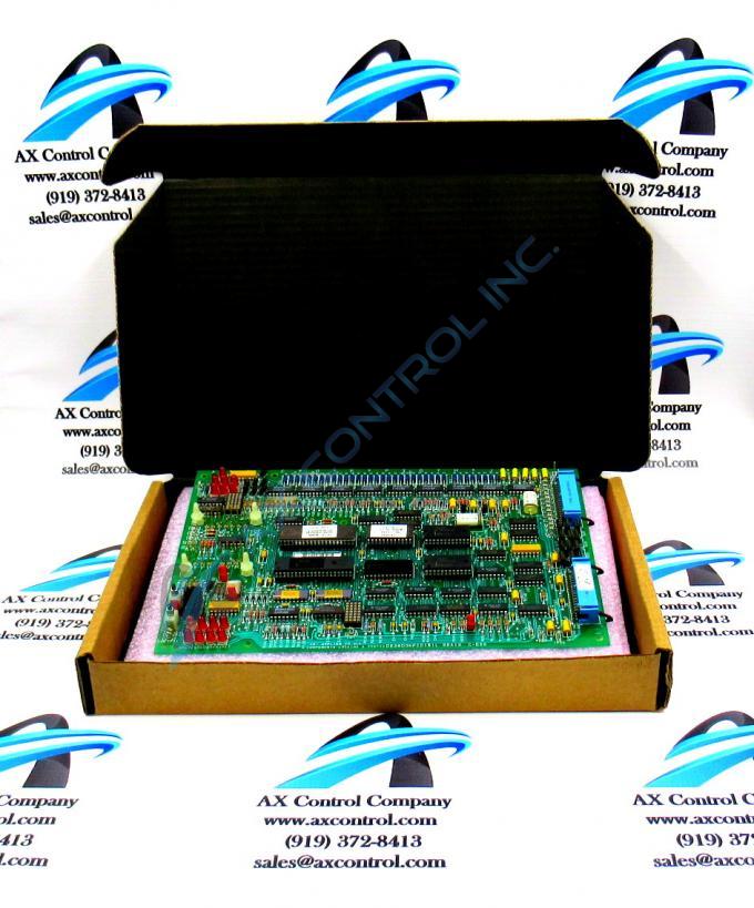
The GE Firing Circuit Board DS3800NFCD1Q1E features 1 hole in each corner for attaching with screws the board to the drive interior. The board is populated with 4 standoffs for attaching a daughter card. The daughter card provides additional processing, connectors, and features. This DS3800NFCD1Q1E Firing Circuit Board device has a group one Mark IV Series product grouping.
Hardware Tips and Specifications
The board is populated with multiple transistor-transistor logic devices. The GE Firing Circuit Board DS3800NFCD1Q1E is also populated with 13 red indicator LEDs and 1 amber indicator LED. The board also has 1 socket for electrically erasable programmable read-only memory (EEPROM) modules. The board is also populated with multiple jumpers and 2 34-pin connectors. The 2 34-pin connectors on the GE Firing Circuit Board DS3800NFCD1Q1E are situated so a technician can connect or disconnect a ribbon cable from the board without removing the board from the drive.
However, it is important to always remove all power from the drive before you touch the board or any other components in the drive. The drive requires several sources of current to operate. For this reason it is important to understand how the drive is installed and how the drive is wired for current. Some of the current is ac current and some is dc current. The dc current is produced through a rectifier that transforms ac current to dc current. To remove the dc current, disable the rectifier by removing a fuse. To remove the ac current, pull a circuit breaker. Once all current is removed, use a testing device to verify that no current exists in the drive before touching components.


