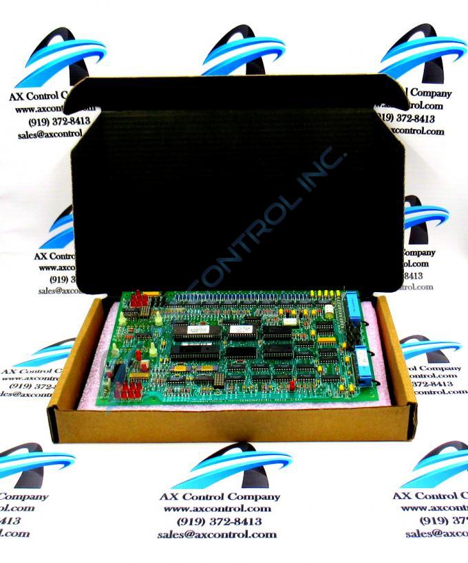
About the DS3800NFCD1Q1H
The GE Firing Circuit Board DS3800NFCD1Q1H features 1 hole in each corner for attaching with screws the board to the drive interior. The board is populated with 4 standoffs for attaching a daughter card. The daughter card provides additional processing, connectors, and features. The board is populated with multiple transistor-transistor logic devices. The GE Firing Circuit Board DS3800NFCD1Q1H is also populated with 13 red indicator LEDs and 1 amber indicator LED. The board also has 1 socket for electrically erasable programmable read-only memory (EEPROM) modules. The board is also populated with multiple jumpers and 2 34-pin connectors.
Because the GE Firing Circuit Board DS3800NFCD1Q1H can have a daughter card installed on it, the board can weight more and be larger than most boards installed in the drive. For this reason care must be taken when installing the board. Use 2 hands when moving the board and never touch the components while carrying the board. You might accidentally bend or break off components. Instead, place your hands on the side edges. Have a clear view of the drive interior while you situate the board in the drive. Then, use 1 hand to insert the screw in the hole in the board and turn the screw driver with the other hand. Repeat the action for the other 3 screws.
If a screw falls out of your hand, retrieve it from the drive interior. The metal screw might touch the board components and cause a short circuit. It might damage the motor or other moving parts if it is jammed in the moving parts.


