About the DS3800NTBD
The DS3800NTBD is a PCB designed to function as a component for the Mark IV series. The Mark IV manages gas and steam turbines and is built with triple-redundant backups on all critical controls and parameters to diminish downtime created by electronics failure.
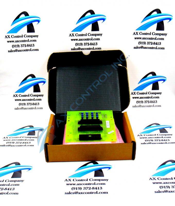
The DS3800NTBD is a termination module for the larger DS3820STMA card. A termination module connects field wiring to I/O cards. Most terminations modules are designed to be DIN rail mounted. Termination modules may be digital, analog, or special function.
The DS3800NTBD is a smaller board. It is built factory drilled and has screw mounts for DIN rails. It also has two other screw mounts located near the center of the board. The board has been marked with the codes NTBD 6DA05 and NTBD 6FA05.
The DS3800NTBD is built with two rows of spare plated through holes (PTH.) It has twelve ceramic-covered metal film resistors, which are placed parallel to each other along the top edge of the board. It is worth noting the resistors do not run in sequential order, but rather run R1, R3, R2, then R4 through R12.
The DS3800NTBD has three PCB mating connectors. This includes one 37-pin female connector (J1,) one 37-pin male connector (J2,) and one 38-pin male connector (J3) that is marked 218A4807P5 87942-5. J1 and J2 also have screw connects at either end of their pin connections.
The DS3800NTBD has twelve jumper switches populating the board. These are located in four rows of three. All are individually labeled. Each switch can be set either to T or to O. It is worth noting these jumper switches begin at “J4,” as the mating connectors on the board have been labeled J1 through J3. The first row of jumpers (J4-J6) is labeled RST. The second row (J7-J9) is labeled ADB2. The third row (J10-J12) is labeled ADB5. The fourth row (J13-J15) is labeled PAR.
General Electric provided all technical support for the DS3800NTBD, including printed material like datasheets and manuals.


