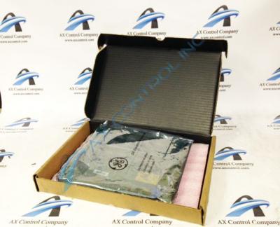
About the DS3810DDDB
The DS3810DDDB is a human machine interface panel designed by GE as a component for their Mark IV series.
The DS3810DDDB is factory drilled and alignment marked on one edge (A through J.) It is built with extractor clips. Extractors allow technicians to install or extract the PCB from tight positions without touching components or circuitry. It also gives them a lever point to pull the board from its position.
The PCB below the HMI panel is built with multiple LEDs. This includes one amber LED that protrudes to the side of the panel, as well as three amber and one red LED that are placed to show through cut-throughs in it. The PCB also has three red LED strips and three amber LED strips. These strips also correspond with cut-throughs in the HMI panel. The red strips have twenty, ten and ten lights respectively. The amber strips have ten, twenty and ten strips respectively.
The HMI panel is connected to the lower board by four screw connectors. It is divided into three sections by two vertical lines. The sections are as follows:
-
Section one. One plunge switch labeled “Reset.” Three amber LEDs. These are labeled DRIVE OK, DATA LINK ACTIVE, and READY TO RUN. One red LED. This is labeled FAULT.
-
Section two. Three numbered groups with individual headers. The first group is headed MOTOR FAULTS. This is numbered one through ten and corresponds to a twenty-light red LED strip. The labels on this strip include 1. Overload 2.Overcurrent 3. Overspeed 4.Overvolts 5.Tach Loss 6.Field Loss 7.Field Overcurrent 8.External Fault 9. PMM Fault 10. Software Trip. The second group is headed CONVERTER FAULTS. This is numbered 11 through 15 and corresponds to a ten-light red LED strip. Labels on this strip include 11.Overload 12. Overcurrent 13. AC Fault 14. DC fault 15. Fault. The third group is headed ALARMS. This is numbered 16 through 20 and corresponds to a ten-light red LED strip. Labels include 16. Motor Overload 17. Converter Overload 18.PMM Overload 19. Memory Enabled 20. Ground Fault.
-
Section three. Three numbered groups with individual headers. The first group is headed DRIVE STATUS. This is numbered 21 through 25 and corresponds to a ten-light amber LED strip. Labels on this strip include 21. Control ready 22. Field on 23. M Closed 24. On Request 25. On. The second group is headed REFERENCE SELECTION. This is numbered 26 through 35 and corresponds to a twenty-light amber LED strip. Labels on this strip include 26. Run Ref. 27. Current Ref 28. Forward Ref 29. Reverse Ref 30.Speed 1 Ref 31. Speed 2 Ref 32. Speed 3 Ref 33. Jog Fwd 34. Jog Rev 35. Creep/Slow. The third group is headed STATUS. This is numbered 36 through 40 and corresponds to a ten-light amber LED strip. Labels on this strip include 36. Zero sleep 37. Reset Reg 38. TuneUp Mode 39. Emergency Stop 40. Alternate Display.
Technical support for the DS3810DDDB was provided by GE. This includes all publications like manuals and data sheets.


