In Stock
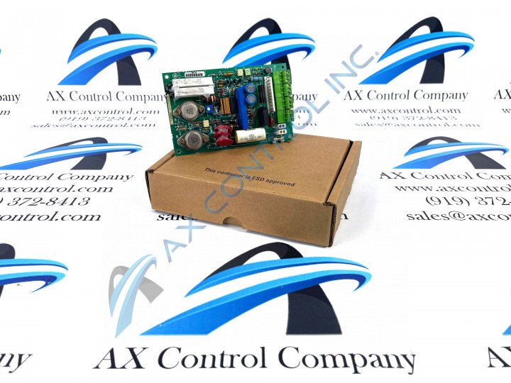
DS200CDBAG1A Image One
3 year warranty

DS200CDBAG1A Image 1
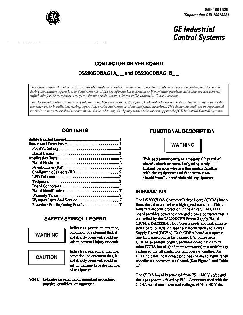
DS200CDBAG1A Image 2
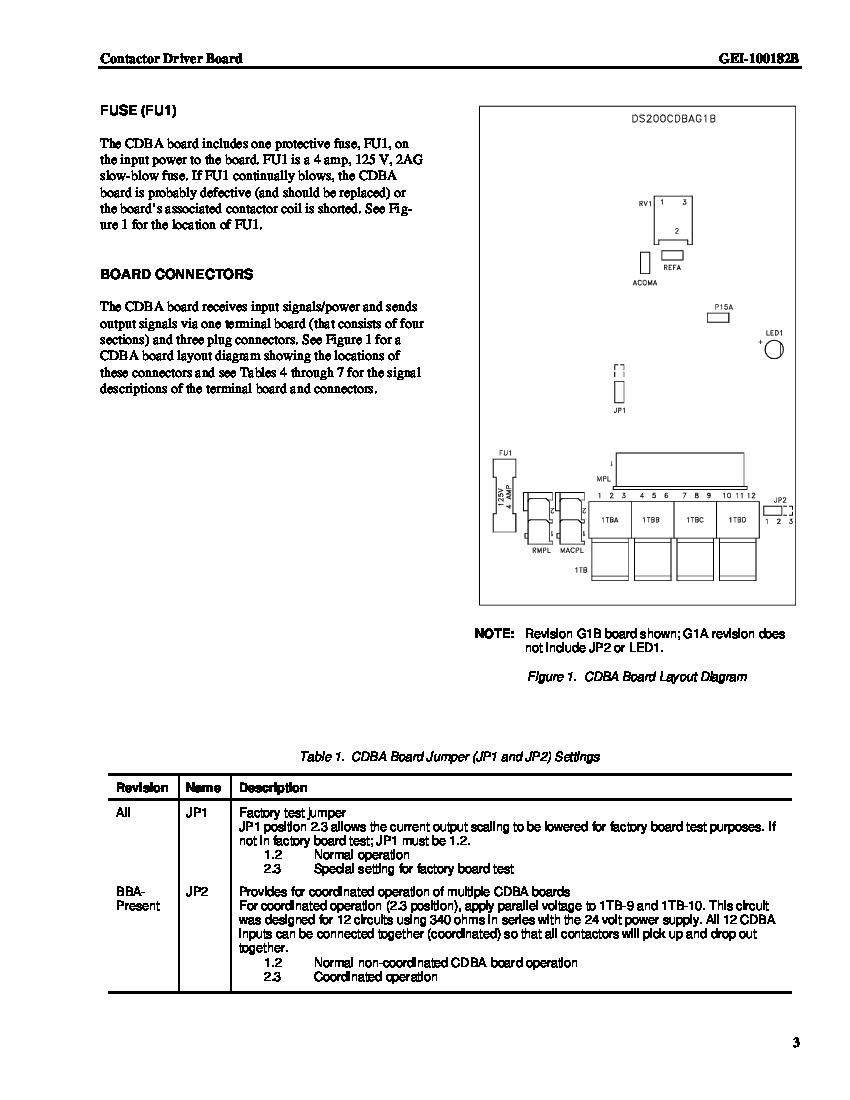
DS200CDBAG1A Image 3
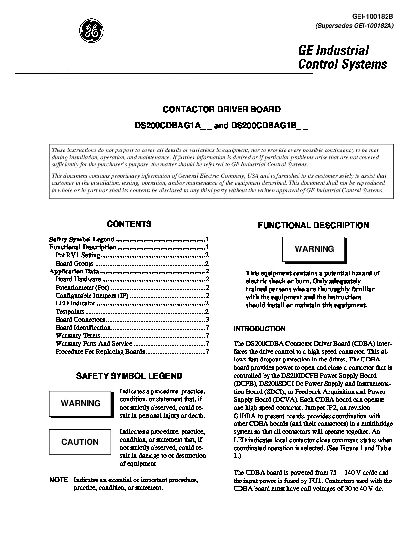
DS200CDBAG1A Image 4

DS200CDBAG1A

    Varying star amount pictures Varying star amount pictures Varying star amount pictures Varying star amount pictures Varying star amount pictures
  • 4.94 (18)
  • Click a star to rate this product
    Varying star amount pictures Varying star amount pictures Varying star amount pictures Varying star amount pictures Varying star amount pictures
  • 4.94 (18)
  • Click a star to rate this product
The DS200CDBAG1A Contactor Driver Board was manufactured by General Electric for the Mark V Series of turbine control systems.

AVAILABILITY:

IN STOCK
SHIPS TODAY

Sell Surplus: Have a DS200CDBAG1A to sell? Sell Now
Exchange Credit: Learn more about our exchange credit program
  • Part Number: DS200CDBAG1A
  • SKU: DS200CDBAG1AGBTC
  • Manufacturer: GE Boards & Turbine Control
  • Series: Mark V DS200

DS200CDBAG1A Technical Specifications

Manufacturer GE General Electric
Series Mark V, DC2000 Adjustable Speed Drives
Part Number DS200CDBAG1A
Functional Description Contactor Driver Board
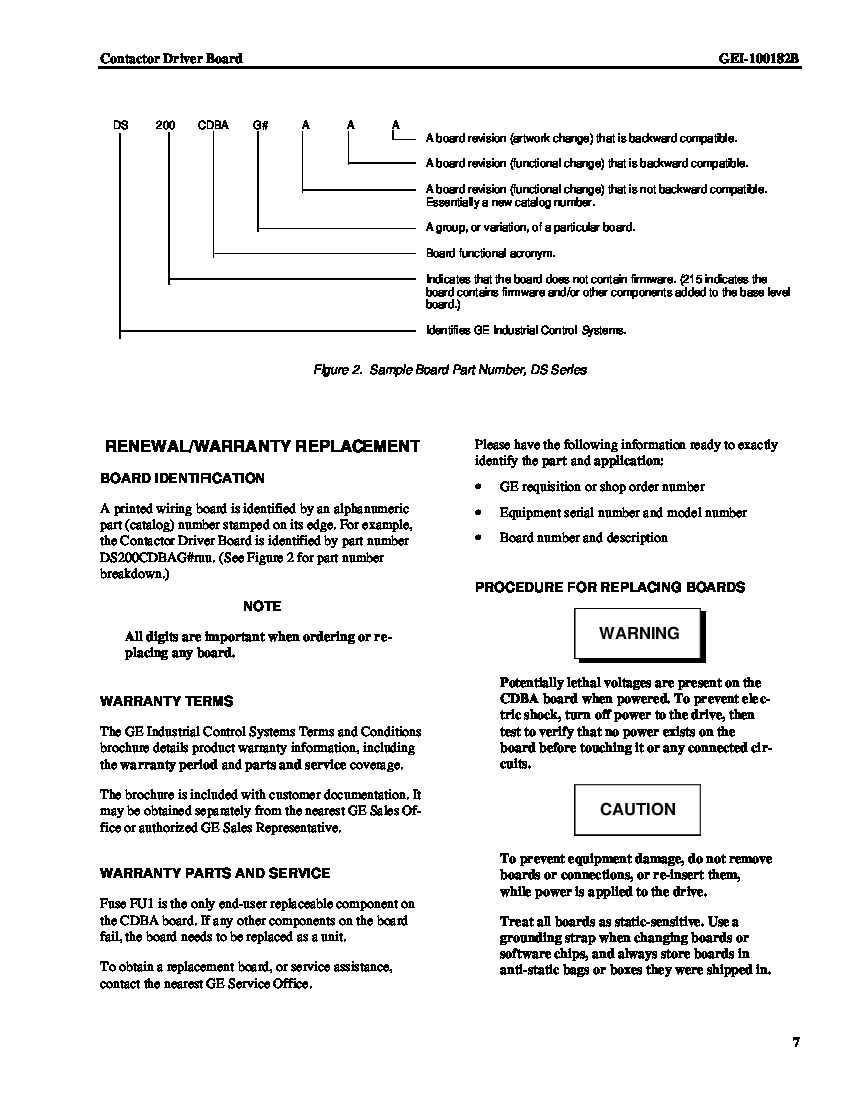
Instruction Manual GEI-100182B
Functional Acronym CDBA
PCB Coating Normal Coating
Functional Revision 1 A

Product Description

This DS200CDBAG1A printed circuit board product offering was, as mentioned above, originally manufactured by the trusted automated industrial manufacturer General Electric, specifically for placement in their now-obsolete Mark V Turbine Control System Series specifically as a Contactor Driver Board. This DS200CDBAG1A product offering's greater Mark V Series is considered obsolete as it has been discontinued for manufacture in the many years following its initial production, and exists as a legacy GE product series. With this being the case, this DS200CDBAG1A product offering's greater Mark V Series can still be considered a relatively well-supported grouping of GE products, given its possession of the final iterance of the Speedtronic control system technology. This DS200CDBAG1A Contactor Driver Board is not the original product of its intended Mark V Series functionality; that would be the DS200CDBAG1 parent printed circuit board missing this DS200CDBAG1A PCB's A-rated functional product revision.

Hardware Tips and Specifications

The GE Contactor Driver Board DS200CDBAG1A opens and closes a contactor within the greater Mark V Turbine Control System Series automated drive assembly in which it was manufactured for. One jumper is located on the board that is reserved for use by the factory during manufacturing. It is used for testing. It is a 3-pin jumper and pins 1 and 2 should remain covered. Do not attempt to change the position of the jumper. This DS200CDBAG1A printed circuit board product offering from General Electric benefits from its normal Mark V Series assembly's inclusion of numerous test points indicating various DS200CDBAG1A Board fault condition statuses. This DS200CDBAG1A Contactor Driver Board has three of these test points in its assembly, including the:

  • TP1 ACOMA CDBA Board Common Reference Point
  • TP2 P15A CDBA Board +15 V dc (± 20%) ACOMA Power Supply Referencr Point
  • TP3 REFA CDBA Board Contactor Driver Voltage Reference Point

Each of the above-listed test points in the assembly of this DS200CDBAG1A Mark V Series product offering has been named through a combination of their test point number, factory-printed nomenclature label, their intended Mark V Series product application, and finally their specific functionality. Consider that the GE Contactor Driver Board DS200CDBAG1A is revised periodically to improve the components, reliability, and operation of the device. However, compatibility between all revisions is assured. For example, you can purchase the latest version of the board and install it in your drive and it will be compatible with the older version you have removed. If the need arises to replace the board, installation is easy and quick. This is due to the design of the drive which provides easy access to the board. For safety reasons and to protect all components, you must remove power to the drive. Wait several minute for all electrical power to be removed. Then test any circuits to make sure all power is removed before touching them with your hands. Open the cabinet door of the drive where the damaged board is located. You might find that there are multiple wires connected to the damaged board. Before you remove them label any that do not have labels to make installation easier. Connector 1TB features a 2-part connector. Use a screwdriver to separate the two sections and disconnect the connectors from the board.

Frequently Asked Questions about DS200CDBAG1A

How does DS200CDBAG1A give protection?
DS200CDBAG1A interfaces the drive control to a high speed contactor which allows fast dropout protection in the drives. 
What hardware is included with DS200CDBAG1A?
Included with DS200CDBAG1A as far as hardware goes, DS200CDBAG1A has: a pententiometer, two configurable jumpers, an LED indicator, three testpoints, a fuse, and wiring connectors as part of the DS200CDBAG1A board.
What do the testpoints on DS200CDBAG1A do?
DS200CDBAG1A has three testpoints. The testpoints on DS200CDBAG1A allow checking of the REFA voltage signal, DS200CDBAG1A board common, and DS200CDBAG1A's +15 V DC power supply.
What manual applies to DS200CDBAG1A?
The manual for DS200CDBAG1A is Manual GEI-100182B. This manual is the GE Industrial Control Systems Contactor Driver Board Manual. We're happy to send you a copy of this manal for DS200CDBAG1A upon request.

Reviews For DS200CDBAG1A

Internal Review
(5.0)

This Mark V Contactor Driver Board DS200CDBAG1A includes three test points, a fuse, wiring connectors, configurable jumpers, an LED indicator, and a potentiometer. These features give the user quite a bit of control over the DS200CDBAG1A and allow for application specific modification. The pot allows users to set contactor driver current. Jumpers are for coordinated operation selection. Test points allow users to check voltage signals. Refer to associated manuals for more information on these devices, including information on the board's protective fuse. Regardless, this board's versatility makes it a highly desirable and well designed PCB. Available for repair and replacement. - AX Control Lead Technician

Repair Services For DS200CDBAG1A

Type Lead Time Price Action
Repair Service 1-2 weeks $1440

Our highly skilled technicians can repair your DS200CDBAG1A. All of our repairs come with a 3 Year AX Control Warranty. Please contact us for additional information about our repair process. To receive the repair pricing and lead time listed above please process your repair order via our website. The following repair options may be available upon request:

  • 48-72hr Rush Repair
  • Detailed Repair Reports
  • AX Control Certificate of Warranty

AX Control Warranty Info

All products we sell are backed by our unparalleled warranty. A warranty certificate will be provided with your order upon request.
All PLCs, HMIs, and Turbine Control Boards: 3 Years
All AC/DC and Servo Drives: 2 Years
All Motors: 1 Year
Learn More