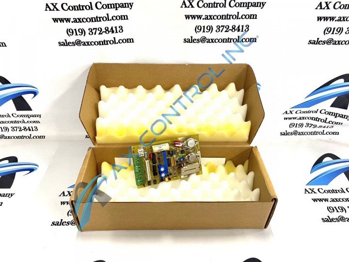
About the DS200CDBAG1B
Greater Product Series Information
This DS200CDBAG1B printed circuit board was originally manufactured for placement in General Electric's Mark V Turbine Control System Series. As you can probably tell by its full extended series name, the Mark V Series that this DS200CDBAG1B product offering belongs to:
- has specific applications in the control and management systems of popular wind, steam, and has turbine automated drive assemblies
- is considered a General Electric legacy series given its eventual manufacturing discontinuation in the years following its initial release
- exists as one of the final General Electric product series to make use of the company's patented style of Speedtronic control system technology.
This DS200CDBAG1B product offering is not the original product of its functionality to feature in the Mark V; that would be the DS200CDBAG1 parent printed circuit board missing this DS200CDBAG1B PCB's B-rated functional product revision.
Hardware Tips and Specifications
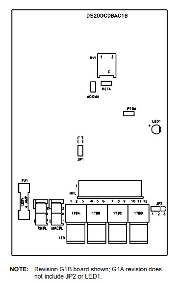
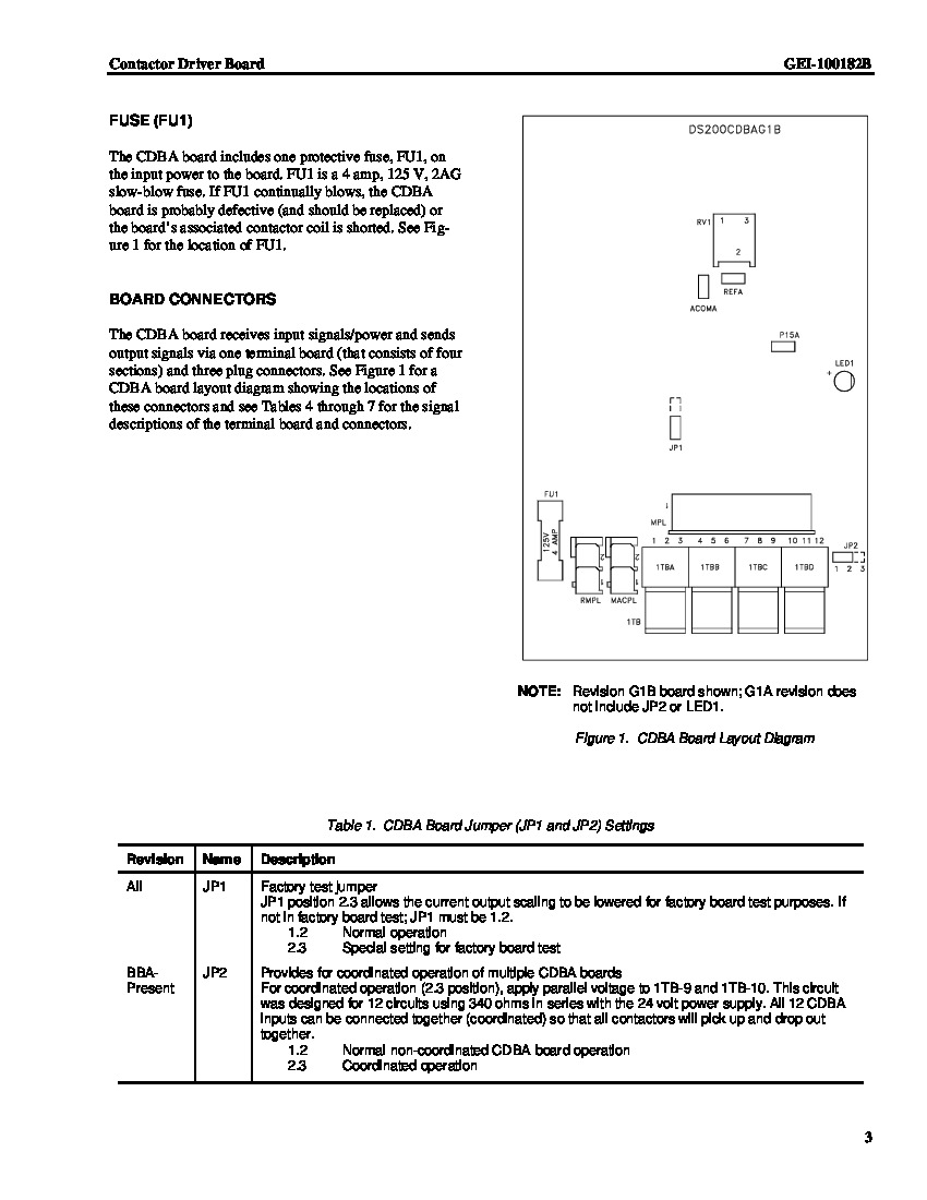
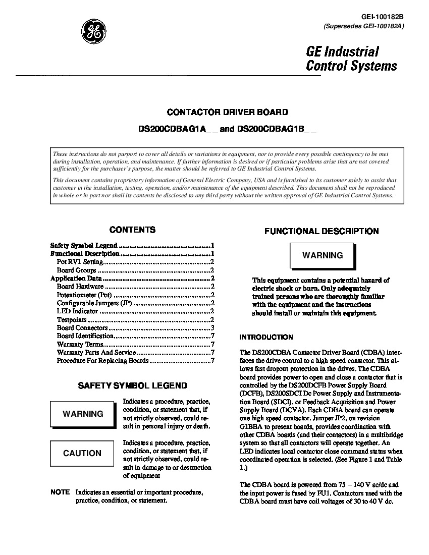
The DS200CDBAG1B is a Contactor Driver Board used in AC2000 and DC2000 Drive Applications. This model was manufactured as a Contactor Driver Board (CBDA) and is primarily used for interfacing between the drive control and the high-speed contactor in the AC/DC2000 drive control cabinet, allowing for quick dropout protection within the drives. Another process the CDBA model performs is providing power to open and close the contactor, which the AC/DC2000 Power Supply Board (DCFB), Feedback Acquisition and Power Supply Board, or the DC Power Supply and Instrumentation Board (SDCI) will control. There is an additional jumper on the DS200CDBAG1B board labeled JP2, which will provide coordination with other CBDA boards and their contactors through a multibridge system in order that all contactors can operate simultaneously. Three testpoints have been included in the assembly of this DS200CDBAG1B printed circuit board for general voltage-regulation purposes. The DS200CDBAG1B PCB's three total testpoints include:
- The ACOMA TP1 CDBA Board Common Reference Point
- The P15A TP2 ACOMA Power Supply Reference Point
- The REFA TP3 Contactor Driver Reference Voltage Point
Hardware Configuration and Installation Specifications
Each of the three listed testpoints in the assembly of this DS200CDBAG1B printed circuit board has been named through a combination of their factory-printed nomenclature labels, test point numbers, and specific intended functionality to the DS200CDBAG1B board and its greater Mark V Turbine Control System Series automated drive assembly. The DS200CDBAG1B board is part of the second group of the CDBA models.
- The G1B revisions can provide coordinated contactor operations
- the JP2 being used for coordinated operation
- the LED1 providing status information when the board has selected coordination mode
- The JP2 must be positioned so it can control the 1TB-9 and 1TB-10 inputs so they can synchronously operate contactors.
- When the JP2 has been set correctly it allows for a solid-state switch to be enabled; the switch will also open the 1TB-1 and 1TB-1 inputs and energizes the 1TB-9 and 1TB-10 inputs so they can proceed to energize the contactor.
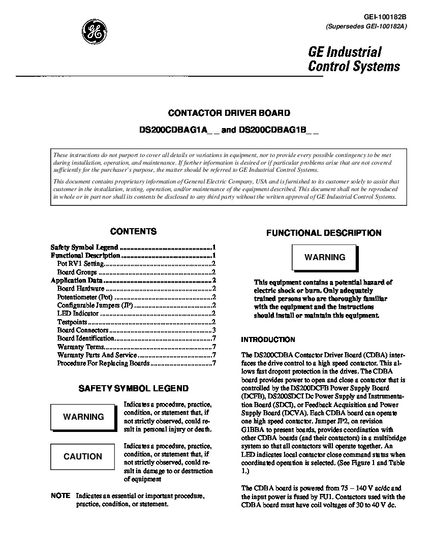
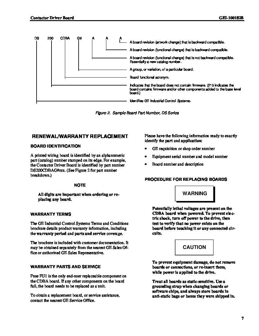
All of the above information comes from the GEI-100182B Contactor Driver Board Instruction Manual. The GEI-100182B manual contains information on the DS200CDBAG1B boards potentiometer, configurable jumpers, troubleshooting, installation, and more. Before making any final purchase decision on this DS200CDBAG1B product offering, it is of utmost importance to understand that this DS200CDBAG1B product offering's singular B-rated functional product revision alters its basic dimensions and performance specifications from their original statuses.


