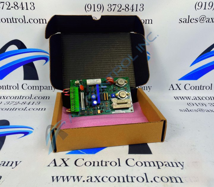
DS200CDBAG1BBB

    Varying star amount pictures Varying star amount pictures Varying star amount pictures Varying star amount pictures Varying star amount pictures
  • 4.92 (13)
  • Click a star to rate this product
    Varying star amount pictures Varying star amount pictures Varying star amount pictures Varying star amount pictures Varying star amount pictures
  • 4.92 (13)
  • Click a star to rate this product
This DS200CDBAG1BBB Contactor Driver Board Assembly was originally created for mass-production by GE Drive Systems, for use in their Mark V Series of products.

AVAILABILITY:

IN STOCK
SHIPS TODAY

Sell Surplus: Have a DS200CDBAG1BBB to sell? Sell Now
Exchange Credit: Learn more about our exchange credit program
  • Part Number: DS200CDBAG1BBB
  • SKU: DS200CDBAG1BBBGBTC
  • Manufacturer: GE Boards & Turbine Control
  • Series: Mark V DS200

DS200CDBAG1BBB Technical Specifications

Manufacturer GE General Electric
Series Mark V
Part Number DS200CDBAG1BBB
Functional Description Contactor Driver Board
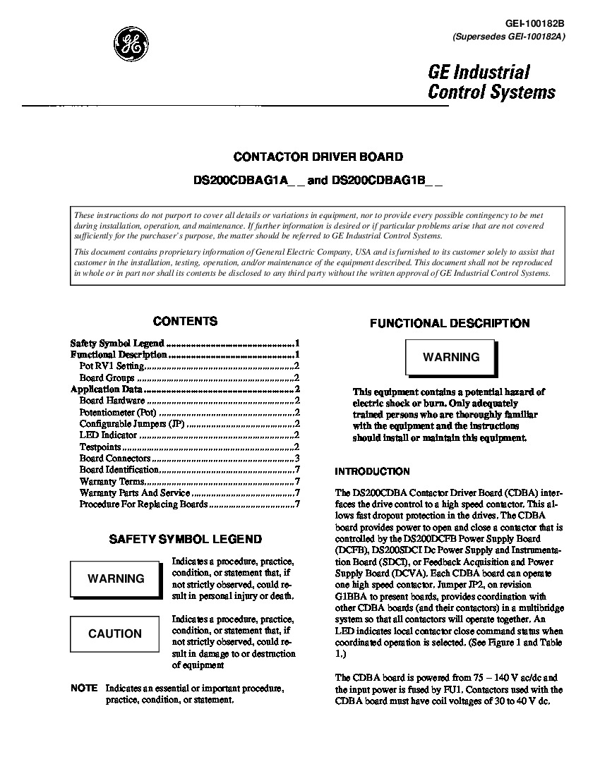
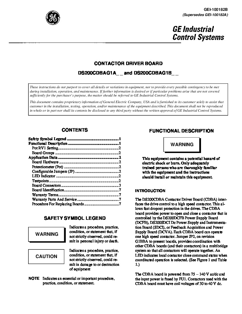
Instruction Manual GEI-100182B
Functional Acronym CDBA
PCB Coating Normal Coating
Functional Revision 1 B
Functional Revision 2 B
Artwork Revision B

About the DS200CDBAG1BBB

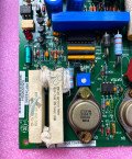
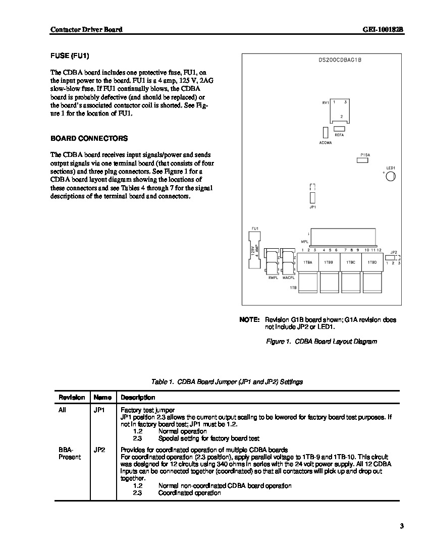
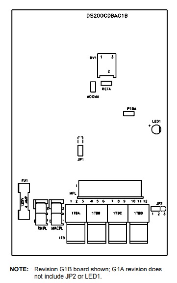
The GE Contactor Driver Board DS200CDBAG1BBB was created for its Mark V Series with the specific application of opening and closing a single contactor. All power, input signals, and output signals are connected to the DS200CDBAG1BBB board through 1 connector on the board (1TB). The 1TB connector is made up of four sections, those four sections being labelled as 1TBA, 1TBB, 1TBC, and 1TBD. Three total plug connectors supply the power and signals to the connector. To remove the connector, use a screwdriver to help pry the connectors apart from the board. Before you remove any cables or connectors of any type from the assembly of this DS200CDBAG1BBB Contactor Drive inherent to the assembly of this DS200CDBAG1BBB Board, it is considered best practice to label all cables to avoid confusion when you install the replacement board.

Additionally, one fuse connector is located on the board. If replacement is necessary use a 4 amp 125V, 2 AG slow-blow fuse. If the fuse blows often, you might suspect that the board needs to be replaced. It might be necessary to troubleshoot the board if you suspect the board is not functioning properly. Test points are on board for you test various functions of the board. You’ll need to use isolated test equipment to test the board. One point is the common reference point. The second test point is used for the 15 V dc power supply reference. The third is for the contactor driver reference.

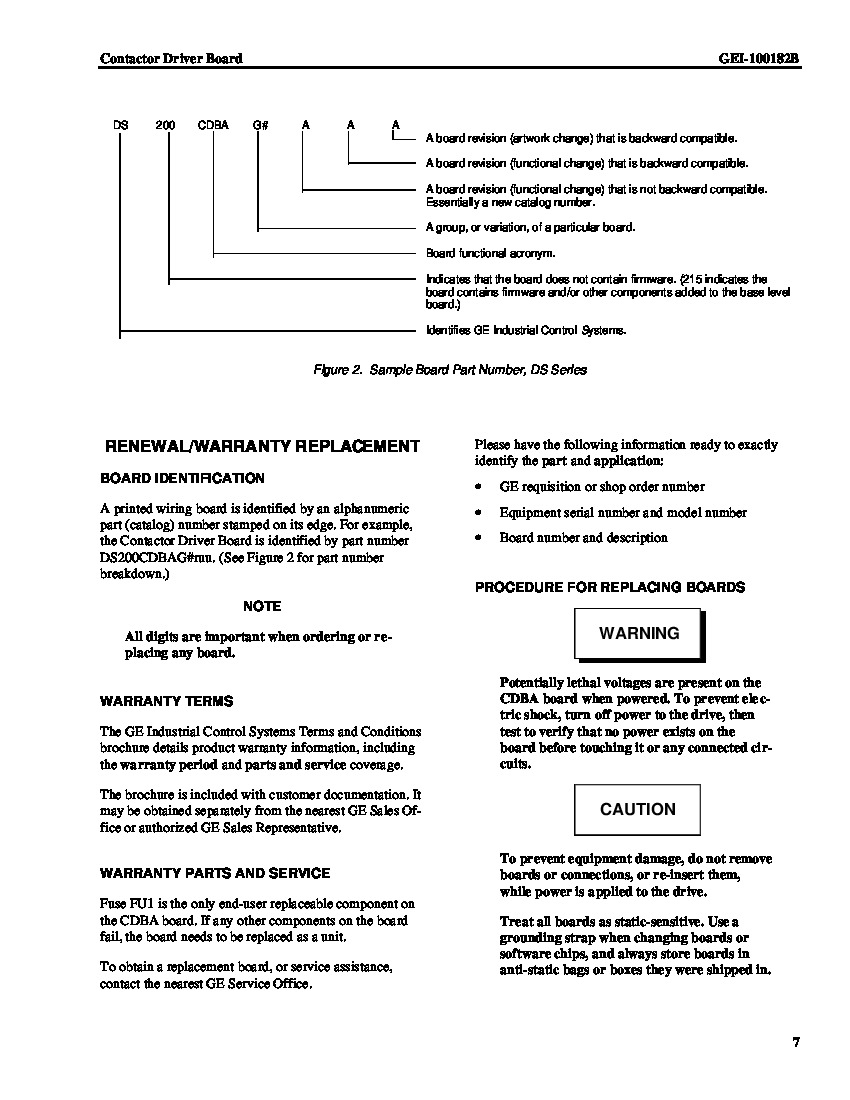
If you call to request service or customer support, be ready to identify the device by the part number before you call. The part number or catalog number is visible on the edge of the board. This DS200CDBAG1BBB part number is considered a functional product number, as it was developed specifically by General Electric to exist as a representation of its product's functionality. Several important hardware traits specific to this GE Contactor Driver Board are mentioned in its DS200CDBAG1BBB functional product number; including its normal assembly type, CDBA functional acronym, domestic location of manufacture, normal PCB coating style, group one Mark V Series grouping, and three B-rated significant product revisions. Please down the identifying information specific to this GE product before you call for service or assistance.

Frequently Asked Questions about DS200CDBAG1BBB

How many groups of DS200CDBAG1BBB boards are there?
There is only one group of DS200CDBAG1BBB boards, but there are two revision levels to the original G1 DS200CDBAG1BBB board. There is revision G1A to DS200CDBAG1BBB and revision G1B to DS200CDBAG1BBB. Revision G1A to DS200CDBAG1BBB do not have the coordinated operation feature and JP2 and LED1 are not included.
How is DS200CDBAG1BBB typically mounted?
DS200CDBAG1BBB is typically mounted on a bracket using standoffs. It's possible you may need to remove the bracket/board assembly from DS200CDBAG1BBB first to gain access to the board standoffs.
How do you know when coordinated operation is selected on DS200CDBAG1BBB?
There's an LED on DS200CDBAG1BBB that indicates local contactor close command status on DS200CDBAG1BBB when coordinated operation is selected.
Where can I find the manual for DS200CDBAG1BBB?
We can send you the manual for DS200CDBAG1BBB. The manual that goes with DS200CDBAG1BBB is the GE Industrial Control Systems Contactor Driver Board Manual, specific to DS200CDBAG1BBB. We'd be happy to send you a link to the manual, Manual GEI-100182B, or we can send you a hard copy of the manual along with a DS200CDBAG1BBB.

Reviews For DS200CDBAG1BBB

Internal Review
(5.0)

This Speedtronic MKV Contactor Driver Board (CDBA) sends output signals and receives input signals from three plug connectors and a terminal board. Associated manuals will provide more information about the location of connectors. This board includes an adjustable potentiometer that can set contactor driver current. This current is usually set at 1.5 amps; however, make sure your replacement board's pot is set to the same current setting as your replacement board to avoid contactor coil failure. - AX Control Lead Technician

Repair Services For DS200CDBAG1BBB

Type Lead Time Price Action
Repair Service 1-2 weeks $1845

Our highly skilled technicians can repair your DS200CDBAG1BBB. All of our repairs come with a 3 Year AX Control Warranty. Please contact us for additional information about our repair process. To receive the repair pricing and lead time listed above please process your repair order via our website. The following repair options may be available upon request:

  • 48-72hr Rush Repair
  • Detailed Repair Reports
  • AX Control Certificate of Warranty

AX Control Warranty Info

All products we sell are backed by our unparalleled warranty. A warranty certificate will be provided with your order upon request.
All PLCs, HMIs, and Turbine Control Boards: 3 Years
All AC/DC and Servo Drives: 2 Years
All Motors: 1 Year
Learn More