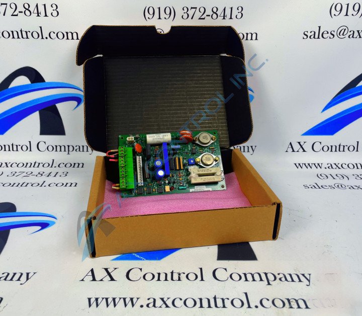
About the DS200CDBAG1BDB
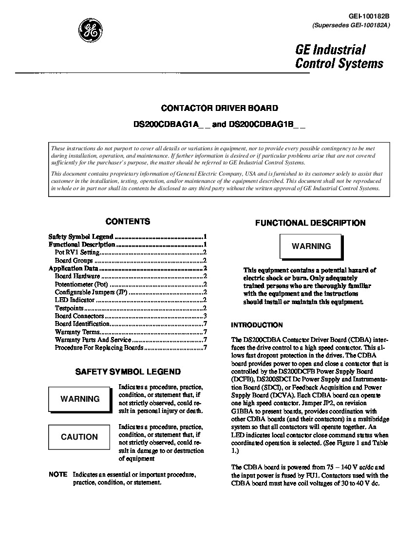
This DS200CDBAG1BDB printed circuit board that exists as a member of General Electric's Mark V Series is more specifically definable as a Contactor Driver Board or Contactor Driver Board Assembly, based on the inclusion of these various functional descriptions in original Mark V Series instructional manual materials. The Mark V Series that this DS200CDBAG1BDB product offering belongs to is a relatively recently-developed product series put out by General Electric that utilizes many of the trappings of previous General Electric Mark Series, including the Speedtronic technology that GE has been developing since the Mark I in the late 1960s. The Mark V Series that this DS200CDBAG1BDB product offering was manufactured for has intended applications in the assemblies of steam, gas, and wind turbine control systems and automated drive assemblies. This CDBA-abbreviated printed circuit board is not the original Contactor Driver Board that was manufactured for the Mark V Turbine Control System Series. The original product of this functionality that was designed and created for the Mark V Series is the DS200CDBAG1 Contactor Driver Board, which is notably missing this DS200CDBAG1BDB product's three-fold revision history.
Hardware Tips and Specifications
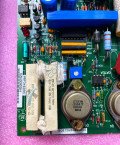
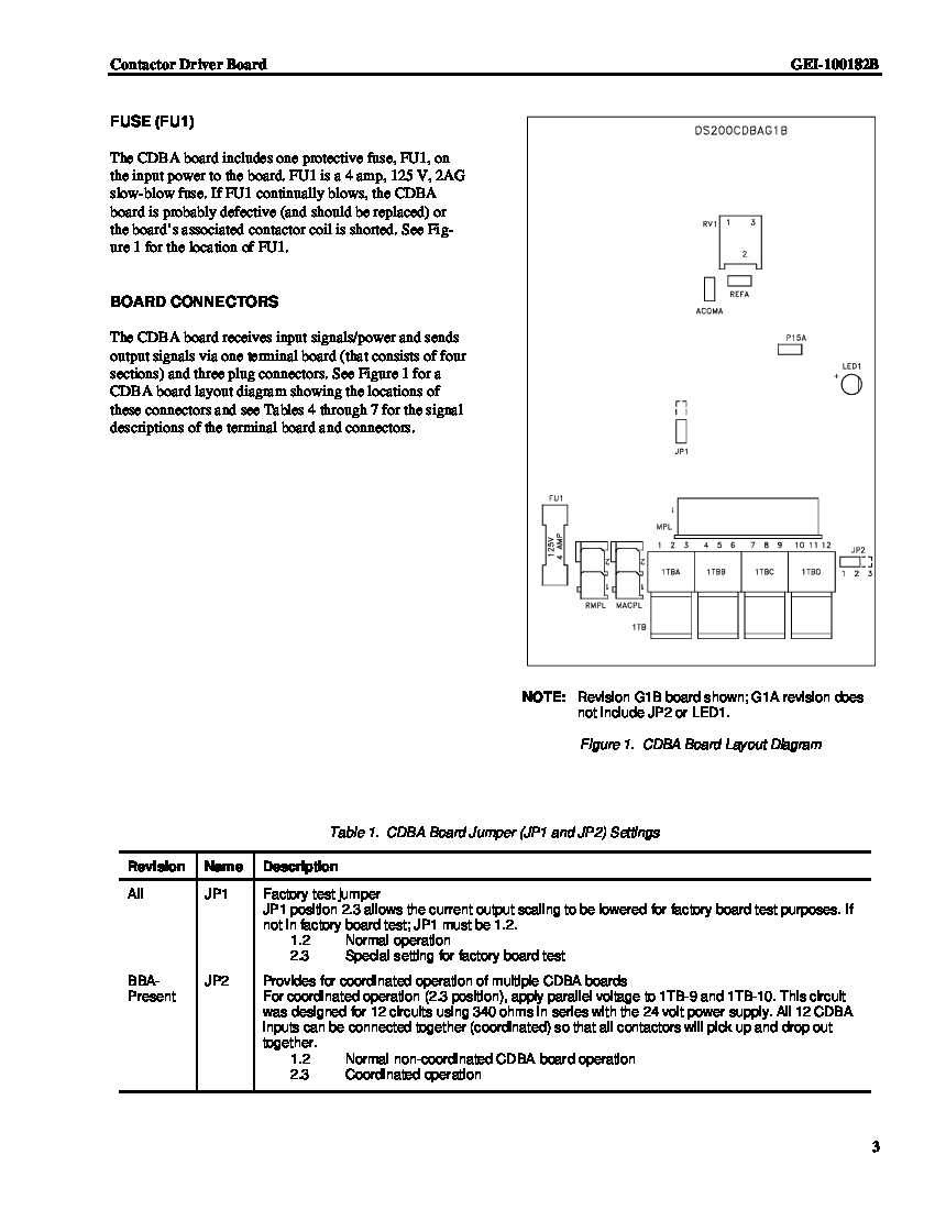
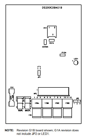
The GE Contactor Driver Board DS200CDBAG1BDB opens and closes a contactor, which introduces its intended function as a contactor driver board. Luckily for our sakes, this DS200CDBAG1BDB PCB is a well-documented Mark V Series product, which allows us to explore many of its individualized hardware component inclusions and specifications. For starters, the DS200CDBAG1BDB features two jumpers that are accessible. One jumper is reserved for use by the factory personnel on the assembly line for testing the board. From the factory the jumper is placed over pins 1 and 2. Do not move the jumper to pins 2 and 3. In some cases you might have multiple contactor driver boards installed in the drive. To enable coordinated operation between the boards, move the jumper to pins 2 and 3. You must provide voltage to connectors 1TB-9 and 1TB-10 on the board to provide the power for coordinated operation. Connectors 1TB-9 and 1TB-10 are included in connector 1TB on the board. All transmitted signals, received signals, and power supply in the assembly of this DS200CDBAG1BDB PCB is through the 1TB connector. Three cables bundled together supply this DS200CDBAG1BDB board with all of its power and signals. These three cables connect to 1TB through three connectors. 1TB is divided into four sections so one connector straddles two sections. One fuse connector is available on the DS200CDBAG1BDB board and it is user replaceable. The board requires a 4 amp fuse, 125VAC at 2AG. If the fuse blows and you replace it, make sure you replace it with an identical fuse. You can easily use your hand to remove the blown fuse and install the replacement, however; you must remove all power to the drive before attempting the procedure and touching the board.
This DS200CDBAG1BDB Contactor Driver Board, while boasting its own set of customizable hardware, is also considered an intuitive and user-friendly General Electric Mark V Turbine Control System Series product, as it makes use of many individual hardware elements for diagnostic testing purposes. Some of these hardware elements include three testpoints, a potentiometer, and an LED indicator. The LED indicator present in the assembly of this DS200CDBAG1BDB Contactor Driver Board is included for the sakes of coordinated operation indications, and will glow bright red to indicate when this DS200CDBAG1BDB device's JP2-labelled jumper is in the normative 2.3 position. The testpoints in the assembly of this DS200CDBAG1BDB printed circuit board are included for the monitoring of this product's REFA voltage signal, CDBA board common, and +15 V dc Power Supply; all crucially important processes for the DS200CDBAG1BDB PCB's normative function. Before making a final purchase decision on this DS200CDBAG1BDB Contactor Driver Board, it is important to consider that this device's originally-disclosed performance specifications and dimensions were likely altered as a function of its inclusion of three significant product revisions.


