About the DS200CPCAG1A
This DS200CPCAG1A printed circuit board product offering from General Electric was originally manufactured for placement in their Mark V Series, as described above. The Mark V from GE is a series of control and management systems and automated drive assemblies and components intended for use in the configurations of various compatible steam, gas, and wind turbines. This Mark V Series is considered a legacy series, as it is no longer actively being manufactured by its original retailer, and is one of the final General Electric Mark product series to make use of their patented style of Speedtronic technology. This DS200CPCAG1A printed circuit board or PCB for short is better-definable through its official functional product description as a Contactor Pilot Card, as it appears in original General Electric or Mark V Turbine Control System Series instructional manual documentation. While this DS200CPCAG1A PCB is certainly definable as a Contactor Pilot Card, it is not the original Mark V Series product of that specific functionality; that would be the DS200CPCAG1 parent Contactor Pilot Card missing this DS200CPCAG1A product offering's A-rated functional product revision.
Hardware Tips and Specifications
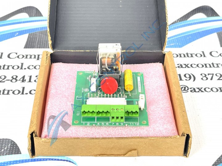
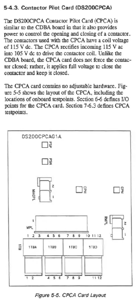
This DS200CPCAG1A Contactor Pilot Card's already-elevated hardware components and component specifications are bolstered further by its inclusion of a sole functional product revision, as mentioned above. The GE Contact Pilot Board DS200CPCAG1A features one 12-pin connector, and two 2-pin connectors. It also features four terminal blocks to connect a maximum of twelve signal wires. The GE Contactor Pilot Board DS200CPCAG1A is also populated with a 24VDC socket power relay. Because the board has terminal blocks the servicer will have to remove the wires attached to them and that will require special consideration, as detailed in original Mark V Turbine Control System Series instructional manual documentation. The DS200CPCAG1A PCB' terminal blocks enable signal cables to attach to the board for processing; some of the wires extending from these terminal blocks transmit signals from the board, while other wires receive signals that are processed by the DS200CPCAG1A board. Unfortunately, this DS200CPCAG1A Contactor Pilot Card is not the most customizable model of General Electric printed circuit board, as it does not possess a singular manually-moveable hardware jumper in its assembly. As defined in original General Electric manual materials once more, the DS200CPCAG1A Contactor Pilot Card behave very similar in function to the CDBA board, another new or reconditioned product offering available for repair or replacement today at AX Control. Both the DS200CPCAG1A Contactor Pilot Card and the similar CDBA board provide power to encourage the opening and closing of a contactor within the Mark V Series.
General Electric offers a series of carefully-developed instructions for establishing terminal connections to the DS200CPCAG1A printed circuit board. Carefully insert the screwdriver and without touching other components loosen one of the terminals and pull out the wire. Do the same for all the terminals that hold wires. Hold the cables by the connector and pull them out of the connector on the board. Use your free hand to steady the board. This is important as a socket power relay is located on the DS200CPCAG1A board and might be damaged when you are tightening the terminals, connecting cables, and securing the board; the relay has moving parts that any jarring might damage. All of the hardware elements and element specifications detailed for this DS200CPCAG1A Contactor Pilot Card above should receive at least some form of protection and insulation from the normal style of General Electric printed circuit board coating that has been applied to individual hardware elements in its assembly on a functional priority basis. This DS200CPCAG1A PCB's originally-introduced performance specifications and dimensions have no doubt been impacted through its addition of an A-rated functional product revision.


