About the DS200CPCAG1ABB
This DS200CPCAG1ABB printed circuit board product offering was manufactured for General Electric's now-obsolete Mark V Turbine Control System legacy series, as indicated before. This DS200CPCAG1ABB printed circuit board or PCB for short's greater Mark V Series is considered a legacy product series due to its necessitated manufacturing discontinuation that took place in the many years following its initial release. While this DS200CPCAG1ABB PCB's greater Mark V Series is a legacy series, it is also one of the final General Electric Mark product series to take advantage of their patented Speedtronic control system technology first released alongside the conception of the Mark I Series in the late 1960s. This DS200CPCAG1ABB PCB is defined in originally-printed Mark V Series instructional manual materials as a Contactor Pilot Board, although the originally-developed product of this specific functional role would be the DS200CPCAG1 parent Contactor Pilot Board missing this DS200CPCAG1ABB PCB's three-fold revision history containing two functional product revisions and a singular artwork configuration revision.
Hardware Tips and Specifications
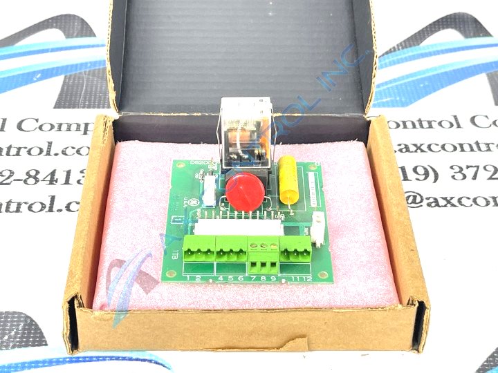
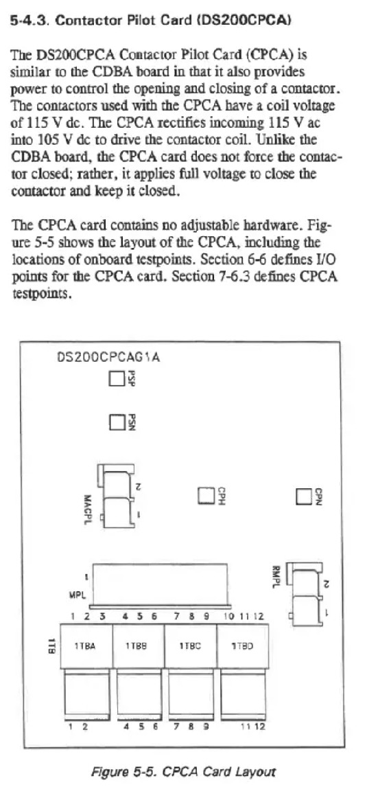
As with any Mark V Series product offering made available to our new and reconditioned inventory here, this DS200CPCAG1ABB PCB's Contactor Pilot Board functionality is introduced through its assembly's acceptance of various functionality-inducing hardware components. The GE Contactor Pilot Board DS200CPCAG1ABB features one 12-pin connector, and two 2-pin connectors. It also features four terminal blocks to connect a maximum of twelve signal wires. The GE Contactor Pilot Board DS200CPCAG1ABB is also populated with a 24VDC 15A socket power relay. According to this DS200CPCAG1ABB device's original instructional manual materials, this DS200CPCAG1ABB PCB's various contactor components have specific coil voltages of 115 V dc. Given this specific voltage, this DS200CPCAG1ABB Contactor Pilot Board is able to convert incoming 115 V ac voltages into 105 V dc voltages, applying full voltage to close its contactors components. The high voltage used in the assembly of this DS200CPCAG1ABB product offering means that its contactors will remain shut after their initial closing. Voltage regulation in the assembly of this DS200CPCAG1ABB Mark V Turbine Control System Series product offering is handled through its assembly's possession of various voltage-limiting hardware components including various rectifiers, capacitors, and diodes. This DS200CPCAG1ABB PCB is reinforced against daily wear and tear damages through its assembly's possession of a thick normal style of PCB surface coating.
The relay has moving parts inside and so requires careful consideration when you install the board in the drive. The relay is easily damaged if it is knocked against a metal structure or other components inside the drive cabinet. And the relay is tall and protrudes from the surface of the board making it easy to hit. When you slide the board into the drive cabinet, make sure you have a good view of the board and the inside of the cabinet. Slowly insert the board and align it with the screws on the rack. With one hand, insert the screws into the holes and with the other hand turn the screwdriver to secure the screws. However, don’t damage the board by securing the board so tight that the screws crack the board. Use washers if they are supplied or were used on the defective board. Then, open the screws on the terminal blocks and insert the wires into the appropriate terminal. With one hand keep the wire inserted into the terminal and use the other hand to tighten the terminal screw. Hold cables by the connector and insert them into the appropriate connector. Gently press them into the connector to insure they are fully seated.


