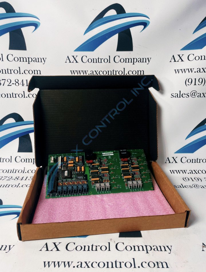
About the DS200CSSAG1AAA
As revealed above, this DS200CSSAG1AAA printed circuit board product offering from the trusted automated industrial retailer General Electric was originally manufactured for their Mark V Series of Turbine Control System products. The Mark V Series that this DS200CSSAG1AAA printed circuit board or PCB for short was first designed and created for is deemable as a legacy product series, given its eventual manufacturing discontinuation in the many years following its initial release. While a legacy series considered obsolete by most of today's factory standards, this DS200CSSAG1AAA PCB's greater Mark V Series is at least well-updated in one respect, as it exists as one of the final General Electric product series to make use of the brand's patented Speedtronic control system technology. The Speedtronic technology featured in this Mark V Series' various product offerings was first released alongside the conception of the Mark I Series in the later 1960s. This DS200CSSAG1AAA printed circuit board is defined in original Mark V Series instructional manual materials as a Cell State Sensor Board, although the original product of this Mark V Series functionality would be the DS200CSSAG1 parent Cell State Sensor Board missing all three of this DS200CSSAG1AAA PCB's A-rated significant product revisions.
Hardware Tips and Specifications
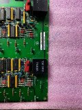
As with any Mark V Series product available here, this DS200CSSAG1AAA PCB's functionality is introduced through its internal assembly's acceptance of a specific series of functionality-inducing hardware components and component specifications. The GE Cell State Sensor Board DS200CSSAG1AAA contains two 40-pin connectors and is 4 inches in height and 11 inches in width. It also contains one 4-pin connector and one 9-pin connector. The GE Cell State Sensor Board DS200CSSAG1AAA also has holes for installing the board in the board cabinet. The drive cabinet is engineered with a rack for the installation of the board and it has matching holes that you can align the board with for installation. When you install the board use any washers that come with the board along with the screws. Given this DS200CSSAG1AAA product offering's attribution to a now-obsolete Mark V General Electric Legacy product series, many of its originally-printed instructional manual materials are not available online for the research purposes of this personalized product page. With this being true, the DS200CSSAG1AAA functional product number gains a new importance, as it reveals many DS200CSSAG1AAA board basic hardware details in a series of functional naming chunks. For instance, the DS200CSSAG1AAA functional product number begins with the DS200 series tag delegating this DS200CSSAG1AAA PCB's normal Mark V Series assembly as well as its domestic original manufacture location. Some of the other relevant details revealed through this DS200CSSAG1AAA PCB's functional product number include its:
- CSSA functional product abbreviation
- Normal PCB coating style
- Group one Mark V Series product grouping
- A-rated primary functional revision
- A-rated secondary functional revision
- A-rated artwork configuration revision
When you install the DS200CSSAG1AAA board, don’t over tighten the screws because it might cause the board to crack, splinter, or break. Only tighten the screws to provide a moderate amount of torque. The washers will help by applying the pressure of the screws to a larger area of the board. When you install the board in the drive make sure you don’t drop the screws, screwdriver, or other supplies in the drive. If you do, stop the installation and find the item that fell in the drive. The fallen items might damage other components. If the items are not found and you apply power to the drive, the items might cause an electric shock, fire, or cause further damage to the drive. The screwdriver and all other tools must be inspected and be certified for the purpose of being used in electrical applications. This is to assure that the insulation material insulates the user against shock.


