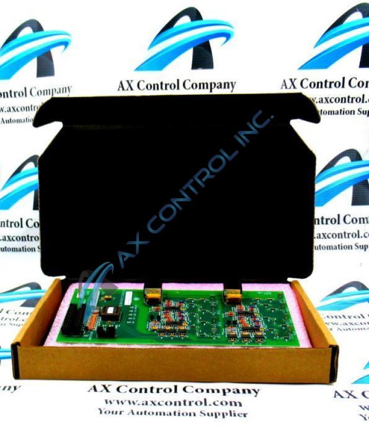
About the DS200CSSAG1B
This DS200CSSAG1B Printed Circuit Board product offering from General Electric was, as mentioned just earlier, originally manufactured for placement in their Mark V Series of turbine control systems and turbine control system component products; within the specific functional role of a Cell State Sensor Board. This DS200CSSAG1B printed circuit board or PCB for short's greater Mark V product series is one of the final General Electric product series to make use of their patented Speedtronic control system technology that was first introduced alongside the rollout of the Mark I Series in the later 1960s. This DS200CSSAG1B Cell State Sensor Board's greater Mark V Series, while one of the final GE product series to utilize the Speedtronic control system technology, exists as a now-obsolete legacy product series, due to is eventual manufacturing discontinuation taking place in the many years since its official original 1960s product series release. This DS200CSSAG1B PCB is not the original Cell State Sensor Board developed for placement in this Mark V Series; that would be the DS200CSSAG1 parent printed circuit board missing this DS200CSSAG1B PCB's B-rated functional product revision.
Hardware Tips and Specifications
As with any Mark V Series product made available to our new and reconditioned inventory here, this DS200CSSAG1B PCB's functionality is introduced through its internal assembly's adoption of functionality-inducing hardware components and component specifications. The GE Cell State Sensor Board DS200CSSAG1B contains two 40-pin connectors and is 4 inches in height and 11 inches in width. It also contains one 4-pin connector and one 9-pin connector. The GE Cell State Sensor Board DS200CSSAG1B can only be installed with the power removed from the drive and one of the first steps in the replacement procedure is to shut off the power. That removes the danger of electric shock and burn from injuring the installers as well as damaging the board and all components. This DS200CSSAG1B printed circuit board is not offered here alongside a plethora of pertinent Mark V Series instructional documentation, given its attribution to the now-obsolete Mark V Legacy product series. This DS200CSSAG1B PCB, with this in mind, benefits from its possession of a General Electric product number; the DS200CSSAG1B functional product number describes many of this DS200CSSAG1B device's hardware traits in functional naming chunks, beginning with the dual-functional DS200 series tag. This initial series tag at the beginning of the DS200CSSAG1B functional product number describes the DS200CSSAG1B Cell State Sensor Board's normal Mark V Series assembly as well as its domestic original manufacture location. Some of the other hardware details revealed in the DS200CSSAG1B functional product number include this DS200CSSAG1B PCB's:
- CSSA functional product acronym
- Normal PCB coating style
- Group one Mark V Series product grouping
- B-rated functional product revision
Before you proceed with an installation or replacement of this DS200CSSAG1B product offering it is necessary to use a testing device to verify that the power is removed. There are some general guidelines to follow concerning the testing device. Make sure the controls on the device are set correctly for the task and also ensure that the tester is calibrated accurately. Only use the approved probes for the tester and inspect them to make sure they are in good working condition. You must have full knowledge of the drive and understand how to test the drive for the presence of electrical power. Once you are satisfied of the absence of power, you can start the procedure. Start by viewing the old board and examining the cables attached to it. Use tape or other means to place labels on the cables that identify the connectors the cables are attached to. Use a screwdriver to remove the screws that secure the board in the drive. Keep the screws and nylon washers out of the way in a safe place.


