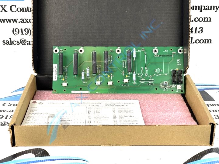
About the DS200CVMAG3A
This DS200CVMAG3A printed circuit board product offering was, as mentioned above, originally manufactured by General Electric, specifically for placement in their Mark V Turbine Control System Series as a Cap/Fuse Voltage Monitor Assembly. While this may be the DS200CVMAG3A product's original instructional manual-introduced functional product description, it is referred to casually as a Generator Control Turbine Board in fringe Mark V Series instructional manual materials. This DS200CVMAG3A printed circuit board or PCB for short's greater Mark V Series has to be considered a now-obsolete legacy General Electric Mark product series, given its eventual manufacturing discontinuation in the many years following its initial release. With this being true, the DS200CVMAG3A PCB's greater Mark V Turbine Control System Series is still considered a well-supported General Electric product series, given its attribution as one of the final General Electric Speedtronic control system technology-guided product offerings. This DS200CVMAG3A printed circuit board's functional Mark V Series role is additionally supported by its attainment of an A-rated functional product revision, which elevates its assembly from an existence as a DS200CVMAG3 parent Cap/Fuse Voltage Monitor Assembly PCB.
Hardware Tips and Specifications
As with any Mark V Turbine Control System Series product made available to our new and reconditioned inventory here, this DS200CVMAG3A PCB's intended Mark V Series functional role is adopted through its internal assembly's possession of several crucial hardware components and specifications. The GE Generator Control Turbine Board DS200CVMAG3A contains two 16-pin connectors and one 2-pin connector. The board also is populated with 6 test points. The 16-pin connectors are used to connect to ribbon cables and the ribbon cables carry control signals to multiple components and boards in the drive. The ribbon cables are easy to damage because of the fine wires that connect to the plastic connector. Always hold the ribbon cable by the plastic connector when you pull it out of the connector on the board. With one hand steady the board to keep it from moving and with the other hand grasp the connector and pull it out. If you can, follow the ribbon cable to the other end and make sure it is fully seated in the connector. This DS200CVMAG3A PCB, as a Mark V Legacy product series product offering, benefits from is possession of a DS200CVMAG3A functional product number displaying many of its more general hardware attributions. Some of the hardware details revealed through this DS200CVMAG3A PCB's DS200CVMAG3A functional product number include its:
- Normal Mark V Series assembly version
- Domestic original manufacture location
- CVMA functional product abbreviation
- Normal PCB coating style
- Group three Mark V Series product grouping
- A-rated functional product revision
If you find the DS200CVMAG3A board is not working properly after you start the drive, you might suspect the ribbon cables and visually inspect the fine wires where they connect to the plastic connector. If you notice that one or more wires might have disconnected from the connector, replace the ribbon cable. The 6 test points are a useful tool for diagnosing the board. The test points are designed to enable you to isolate and test one specific circuit in the board. Only a qualified individual should be testing the board due to the current in the board and the surrounding components. Make sure you use a tester that is suitable for the purpose and is calibrated for the task. Before making any final purchase decision on this DS200CVMAG3A printed circuit board product offering, it is crucial to understand that its originally-introduced performance specifications and dimensions have surely been impacted by its assembly's adoption of an A-rated functional product revision.


