

❮


❯


DS200DCFBG1B
- 4.75 (32)
The DS200DCFBG1B Power Supply Board was manufactured by General Electric for use in Mark V, AC2000, CB2000, DC2000, FC2000, ME2000, and EX2000 Turbine Applications.
About the DS200DCFBG1B
The DS200DCFBG1B is a power supply board manufactured by General Electric for the Mark V board series. Turbine applications such as AC2000, CB2000, DC2000, FC2000, ME2000, and EX2000 use this board in their systems. When installed, this card can provide both control level power and enclosure fan power to the turbine application. The EX2000 system utilizes the DS200DCFBG1B differently from the other drive systems listed. This board has includes the circuits listed below:
- Control-level power supplies
- Motor field power circuits
- Armature current and voltages
- Motor field currents
- AC line current
- Driver circuits for SCR generators
The DS200DCFBG1B communicates with the SDCC or LDCC control boards by providing an analog representation of the motor voltage. On the board the the DIP switch labeled SW6 can be used to actively scale the modify the motor voltage feedback. Additionally, this board contains amplifier circuits that allow it to communication the voltage feedback signals to the SDCC and LDCC control cards. Similarly, it includes a voltage-controlled oscillator that efficiently converts input voltages to frequency signals that are then sent through connector 1PL to the controls cards.
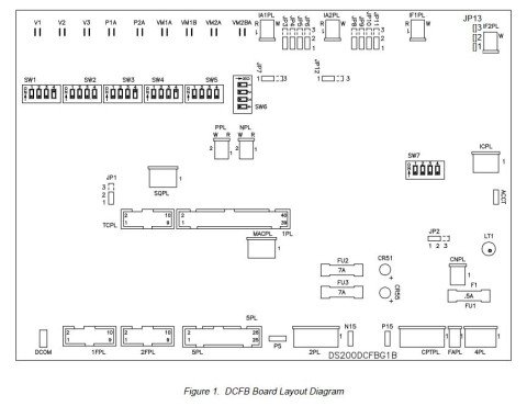
The DS200DCFBG1B board layout diagram is shown below and provides information regarding the placements of all jumpers, dip switches, stab connectors, connectors, and fuses:
Hardware Tips and Specifications
This DS200DCFBG1B printed circuit board or PCB for short comes with its own series of hardware component inclusions and specifications that introduce its intended Mark V Series functionality. Voltages rated between 38 and 115 VAC can be directly supplied to the board via the control power transformer. Frequencies for the board are dependent upon the input voltage, but can range from 0 to 500 kHz.The board features a number of circuits that work to power the board and the installed drive. The DS200DCFBG1B is comprised of motor field power, driver, AC/DC monitoring, and control level supply circuits.
The twelve jumpers and seven DIP switches found on the board provide users with configurable system options; fuse switch diagnostics are presented using the two LED and one neon indicator lights found on the board. Any jumper present on the base circuit board of this DS200DCFBG1B product would be accompanied by the JP factory-printed nomenclature label, while with the DIP switches, it is the SW label. Three protective fuses prevent any interruptions in power supplies. DS200DCFBG1B Voltages can be monitored using the five test points integrated on the board. Similarly to this DS200DCFBG1B device's fuses, this DS200DCFBG1B product makes use of a specific series of connectors for interfacing opportunities with other Mark V Series products. This DS200DCFBG1B Power Supply Board utilizes eighteen total plug-style connectors and nine additional stab-style connectors, with various functions as listed in the DS200DCFBG1B Data sheet supplied above once again. The purposes of this DS200DCFBG1B Board's three included LED indicators are explained in detail in the original DS200DCFBG1B instructional manual attached above, and each LED indicator is accompanied by its own factory-printed nomenclature label. The LED diagnostic indicators included in the DS200DCFBG1B PCB's assembly include:
- The CR51 FU2 dc regulator status LED indicator
- The CR55 FU3 dc regulator status LED indicator
- The LT1 FU1 ac line status LED indicator
Both the CR51 and CR55 LED diagnostic indicators in this DS200DCFBG1B Power Supply Board's external assembly exist as basic red-glowing led status indicators, whereas this DS200DCFBG1B printed circuit board's LT1-labeled LED diagnostic indicator truly exists as a neon lamp. These LED indicators have been named through a combination of their factory-printed nomenclature labels and their functionality relative to the DS200DCFBG1B Power Supply Board and its greater Mark V Series automated drive assembly. Additionally, five total test points have been made available to the normal Mark V Series assembly version inherent to this DS200SDCIG1A product. Each of these test points is included to identify for a specific value pertaining to voltage signal, DS200SDCIG1A Board common, or ACCT signal statuses.
Before making a final purchasing decision on this DS200DCFBG1B Power Supply Board, it is important to realize that its originally-introduced performance specifications have been impacted by its insertion of a B-rated functional product. Manufacturer provided installation and storage parameters for both the DS200DCFBG1B and the installed drive should be followed. These will prevent any accidental or preventable damages to the power supply board or broader application. For a complete guide to wiring and installing the board, please reference the device’s manual and data sheet.
AX Control’s friendly and trusted sales staff is available to help with all of your automation needs. For current prices on availabilities and prices on DS200DCFBG1B and other parts, please contact our office by phone or email.
AX Control Warranty Info
All products we sell are backed by our unparalleled warranty. A warranty certificate will be provided with your order upon request.
| All PLCs, HMIs, and Turbine Control Boards: | 3 Years |
| All AC/DC and Servo Drives: | 2 Years |
| All Motors: | 1 Year |


