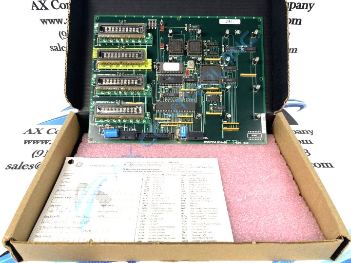
About the DS200DKLBG1ABB
The DS200DKLBG1ABB Power Connect Board from General Electric was originally engineered for production within the Mark V Series of turbine control systems and turbine control system components. This DKLB-abbreviated product offering exists as a secondary version of the original Power Connect Board; altering the original Mark V Series product through its inclusion of three significant product revisions. While this DS200DKLBG1ABB printed circuit board or PCB for short does have a full three-fold revision history, it is not considered to possess any sort of special assembly type, as evidenced through the presence of the DS200 series tag in the DS200DKLBG1ABB functional product number. This DS200DKLBG1ABB PCB, while possessing an official functional product description as a Power Connect Board, is also referred to in original General Electric documentation as a Drive Control/LAN Communications Board, in an election to describe some of the bonus functionality of this product.
Hardware Tips and Specifications
The DS200DKLBG1ABB Power Connect Board featured on this customized product page makes use of a relatively high number of hardware components and component specifications to achieve all of its Mark V Series-intended functionalities. For starters, the GE Drive Control/LAN Communications Board DS200DKLBG1ABB features four displays with 10 characters on each display. This Mark V Series product offering also features 16 LEDs and three jumpers, with one 40-pin connector. The board dimensions are 8.5 inches by 11 inches and it has one hole in each corner for installation in the board rack in the drive. When you arrange the board in the rack, you will find that the holes on the board align with matching holes in the rack structure. During manual-informed replacement, you can remove the four screws from the board you are removing and keep the screws together for use when you attach the replacement board. If the screws also have washers keep them also and use them when you install the new board; they help protect the board from damage if the screws are attached too tightly. If the screws are too tight they might crack the board or otherwise damage the board.
The three jumpers each has an identifier printed on the board. One jumper is identified as JP1, one as JP2, and one as JP3. Some of the jumpers are available to change the configuration of the board. The written material supplied with the original board describes the functions of the jumpers; when you replace the original board, you can and should match the settings of the jumpers on the defective board on the replacement board.


