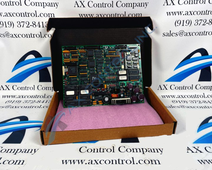
About the DS200DMCBG1AJE
This DS200DMCBG1AJE printed circuit board product offering from General Electric was originally, as mentioned in brevity before, manufactured specifically for placement in their Mark V Turbine Control System Series. As you have probably been able to infer based off of its full extended series name, the Mark V Series that this DS200DMCBG1AJE printed circuit board or PCB for short belongs to has specific applications in the management and control systems of popular and compatible wind, gas, and steam turbine automated drive assemblies. While this DS200DMCBG1AJE PCB's greater Mark V Series may have some relatively recently-developed applications, it must be considered obsolete as a whole given its manufacturer-issued production discontinuation that took place in one of the many years following its initial General Electric product series release. With this being true, this DS200DMCBG1AJE PCB's greater Mark V Series is still quite the highly-acclaimed General Electric Mark product series; as it exists as one of the final-developed General Electric product series to make use of the company's patented Speedtronic control system technology.
Hardware Tips and Specifications
The GE DOS DUP Processor Board DS200DMCBG1AJE contains three 26-pin connectors, one 40-pin connector, and 19 jumpers. The board also has 2 LEDs. The LEDs on the GE DOS DUP Processor Board DS200DMCBG1AJE provide the user with a quick and easy way to keep informed on the processing activity of the board. The LEDs are identified as CR2 and CR12 on the board and they are located together in one corner of the board. If you have reason to suspect a problem with the board, it is best to first inspect the LEDs. You can open the board cabinet door and find the board. Then, examine the LEDs and note the activity indicated by the LEDs. This DS200DMCBG1AJE printed circuit board is not the originally-introduced product of its specific Mark V Series functionality; as evidenced by its DS200DMCBG1AJE functional product number's inclusion of several trailing, revision-indicating alphanumeric digits. The original DOS DUP Processor Board manufactured for placement in GE's Mark V Turbine Control System Series is the DS200DMCBG1 parent printed circuit board missing all three of this DS200DMCBG1AJE PCB's three significant product revisions rated at grades of A, J, and E respectively. Generally, voltage suppression and limitation in the normal Mark V Series assembly of this DS200DMCBG1AJE product offering would be handled by a series-standardized group of voltage limitation-aimed hardware components such as various diodes, rectifiers, capacitors, and resistors.
The presence of this DS200DMCBG1AJE PCB's LED diagnostic processing information on this DS200DMCBG1AJE personalized product page is more reminiscent of this DS200DMCBG1AJE PCB's lack of surrounding instructional manual materials online than it is of their true importance. With this being the case, the DS200DMCBG1AJE functional product number itself exists as a primary source of DS200DMCBG1AJE Board hardware component and component specification information; coding for various DS200DMCBG1AJE Board details in a series of functional naming chunks. For instance, the DS200DMCBG1AJE functional product number starts off with the dual-functional DS200 series tag describing this DS200DMCBG1AJE PCB's normal Mark V Series assembly as well as its domestic original manufacture location. Some of the other valuable hardware traits revealed in the DS200DMCBG1AJE functional product number include this DS200DMCBG1AJE PCB's:
- DMCB functional product abbreviation
- Group one Mark V Series product grouping
- Normal PCB coating style
- A-rated primary functional revision
- J-rated secondary functional revision
- E-rated artwork configuration revision
Another quick indicator of a problem with the board is to inspect the fuses. The DS200DMCBG1AJE features two fuses that protect different circuits in the board. If you find that one fuse is blown, it indicates that a power surge or other issue occurred that exposed the board to a over-voltage condition. To replace the fuse, first power off the drive and use a tester to verify that all power is removed. The tester must have all controls set correctly for the purpose and make sure the tester is fully calibrated. Position yourself in front of the drive cabinet so that you have a clear view of the board, if possible. With one hand, remove the fuse by pulling it out of the retainer. Use the same hand to position the replacement fuse over the retainer, then press it into the retainer.


