About the DS200DPCBG1A
This DS200DPCBG1A General Electric printed circuit board product offering was originally manufactured for placement in General Electric's Mark V Turbine Control System Series. As you can probably tell by its full extended name, the Mark V Series has specific applications in the management and control systems of wind, steam, and gas turbine automated drive assemblies, and is considered a General Electric legacy series due to its eventual manufacturing discontinuation by its original retailer. With this being true, the Mark V Turbine Control System Series that this DS200DPCBG1A product offering belongs to is also notable as one of the final General Electric Mark control system series to feature the patented Speedtronic control system technology. This DS200DPCBG1A printed circuit board or PCB for short is truly better-definable as an IOS + Power Connect Board, its original functional product description that appears in Mark V Turbine Control System Series instructional manual materials. The original IOS + Power Connect Board manufactured for placement in the Mark V Series is the DS200DPCBG1 parent printed circuit board missing this DS200DPCBG1A PCB's A-rated functional product revision.
Hardware Tips and Specifications
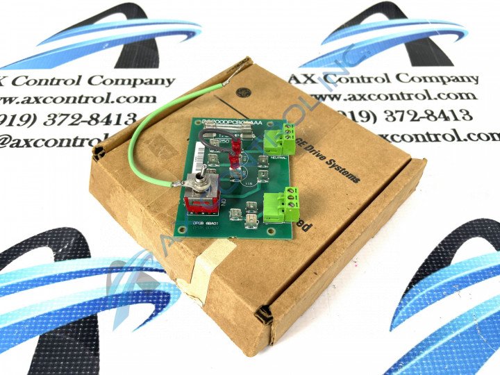
As with any Mark V Series product offering, this DS200DPCBG1A PCB has a specialized assembly with its own set of functionality-introducing hardware components and component specifications. The GE IOS + Power Connect Board DS200DPCBG1A features two wire terminal blocks to attach a maximum of 6 signal wires. The GE IOS + Power Connect Board DS200DPCBG1A also is populated with 1 fuse and one toggle switch. While this DS200DPCBG1A PCB's main functional components can be defined as its wire terminal blocks and integral toggle switch, this DS200DPCBG1A product offering also seems to make use of many Mark V Series-standardized hardware components, specifically those components intended for voltage regulation or suppression. The DS200DPCBG1A PCB makes use of several diodes, rectifiers, capacitors, and integrated circuits in its assembly for these purposes, and is additionally reinforced through the presence of a rudimentary insulated layer of normal style PCB coating. The normal style of PCB coating insulates, envelops, and protects individual DS200DPCBG1A IOS + Power Connect Board hardware components on a functional priority basis through its chemical application. Even the numerous factory-drilled holes meant for convenient installation of this DS200DPCBG1A printed circuit board have been ringed with an insulated material, in observance of potentially-present damaging surface voltages. Before making any final purchase decision on this DS200DPCBG1A product offering, it is crucial to remember that it has been altered from its originally-introduced performance specifications and dimensions through use of its singular A-rated functional product revision.
When you replace the GE IOS + Power Connect Board DS200DPCBG1A it is necessary to connect the signal wires to the same connectors on the terminal blocks. To do that and also to properly disconnect the wires from the terminal blocks requires that you follow some guidelines, as indicated in this DS200DPCBG1A product's original instructional manual. Notice that the terminal blocks have identifiers for the individual connectors. Diagram the terminal blocks to provide yourself a plan showing the identifiers and also what terminals have wires attached to them. Tape on the signal wires the identifier they are attached to on the terminal block. However, only touch the board when power is removed from the drive. Consult with an electrician who is familiar with the installation of the drive to understand how the drive is powered. The drive receives power from a power supply and the best practice is to remove the fuses from the power supply to remove power from the drive. Keep the fuses in a safe place but removed from the power supply so that someone doesn’t replace the fuses while the servicer is working on the replacement procedure. Use a screwdriver to loosen the screw that retains the wire in the terminal. However, make sure the screwdriver doesn’t touch any other components in the drive. The screwdriver might scratch a board or damage components or cause components to fall off the board.


