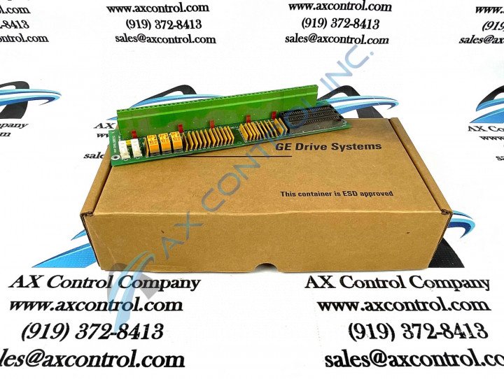
About the DS200DTBAG1
As identified in the brief product description posited above, this DS200DTBAG1 printed circuit board product offering from General Electric is a Digital Contact Terminal Board originally designed and produced to act as a component member of their Mark V Turbine Control System Series. A rather self-explanatory General Electric product series; this DS200DTBAG1 PCB's greater Mark V Series has specific applications in the control and management systems of popular, compatible gas, steam, and wind turbine automated drive assemblies. This DS200DTBAG1 PCB is the originally-produced device of its specific Mark V Series functionality; given its DS200DTBAG1 functional product number's lack of any trailing, revision-indicating digits. While this DS200DTBAG1 PCB's greater Mark V Series does have some alternative energy applications, it has to generally be considered a now-obsolete legacy product series; given its eventual manufacturing discontinuation that took place in one of the many years following its initial GE product series release. While generally obsolete, this DS200DTBAG1 product offering's greater Mark V Series is still very much a hot commodity on the general automated industrial marketplace, as it exists as one of the lastly-developed Mark product series to make use of the patented Speedtronic control system technology first introduced alongside the rollout of the initial Mark I Series in the late 1960s.
Hardware Tips and Specifications
As with any General Electric printed circuit board product offering available for purchase or repair here, this DS200DTBAG1 PCB makes use of its own specialized series of functionality-inducing hardware components and component specifications. The GE Digital Contact Terminal Board DS200DTBAG1 features two terminal blocks that each connect a maximum of 95 wires. DS200DTBAG1 also features 5 jumpers and two 2-pin connectors. Generally, voltage suppression and limitation in the normal Mark V Series assembly of this DS200DTBAG1 product is handled by its series-standardized selection of voltage-suppressing hardware components including various styles of capacitors, transistors, resistors, and integrated circuits. After you disconnect the drive from electric power you can begin to replace the drive. Due to the 190 signal wires connected to the terminal blocks you must document where the wires are connected. To make it easy the terminals have a letter and number designation and you can attach the designation information on the wire. If you have a large number of wires attached to the terminal, allow plenty of time to identify the terminals on the wire. Do the same with the other connectors. As with any individual hardware component visible on the base circuit board product offering, this DS200DTBAG1 PCB's set of Mark V Series connectors are all accompanied by their very own factory-printed nomenclature labels. Some of this DS200DTBAG1 PCB's various connectors include the:
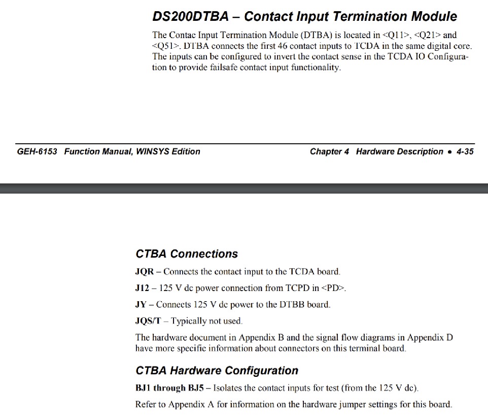
- JQR TCDA Board Contact Input Connector
- J12 TCPD Board 125 V dc Power Connector
- JY DTBB Board 125 V dc Power Connector
- JQS/T Connector
All of the aforementioned connectors in the normal Mark V Series assembly of this DS200DTBAG1 product offering have been named through unique combinations of their factory-printed nomenclature labels their Mark V Series compatible products, and finally the type of signal that they were designed to transmit from the assembly of this DS200DTBAG1 Device. This DS200DTBAG1 PCB's JQS/T Connector has not been named as such as it exist solely as a vestigial structure not meant to be accessed during normative functionality of the DS200DTBAG1 product outside of factory testing purposes. The jumpers are set to define the configuration of the board and so to ensure the replacement board works the same as the old board, you have to set the jumpers in the same positions. Some of the jumpers are only used at the factory for testing purposes and cannot be moved because the configuration in the alternate position is not supported. Regardless, record the position of all five jumpers on the old board using the designation printed on the board which is prefixed with JP. Like, for example JP1, JP2, and JP3. In terms of its installation, before attempting a replacement of the DS200DTBAG1 Board is is crucial to setup up the wrist strap by connecting one end to a metal surface that is paint free and wrap the other end around your wrist. Open the protective bag and slid out the board and rest the board on top of the bag.


