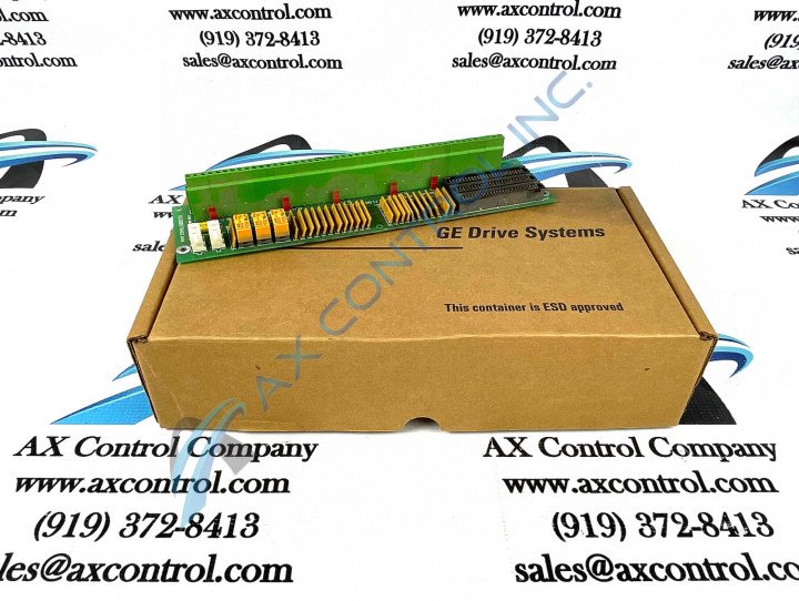
About the DS200DTBAG1AAA
This DS200DTBAG1AAA Contact Input Termination Board was originally manufactured, as described above, for General Electric's Mark V Turbine Control System Series. As you can probably tell by its full extended name, the Mark V Series has specific applications in the management and control systems of wind, steam, and gas turbine automated assemblies, and is considered a General Electric legacy series as its manufacture has been discontinued in the years following its initial release. While considerable as a legacy series, the Mark V Turbine Control System Series that this DS200DTBAG1AAA product offering exists in is also one of the final General Electric Mark Series to make use of the Speedtronic control system technology in the assemblies of its various products. This DS200DTBAG1AAA printed circuit board, while definable as a Contact Input Termination Board in its own right, is not the originally-developed product of this functionality; that would be the DS200DTBAG1 Contact Input Termination Board missing this DS200DTBAG1AAA device's three significant product revisions.
Hardware Tips and Specifications
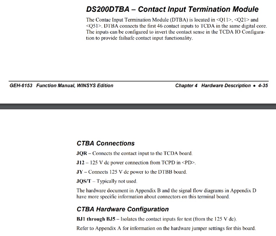
Given this DS200DTBAG1AAA product offering's specific intended functionality, it should come as no surprise that this DS200DTBAG1AAA PCB utilizes its own series of functionality-introducing hardware components and component specifications. The Digital Contact Terminal Board DS200DTBAG1AAA features two terminal blocks that connect a maximum of 95 wires. This unit also features five jumpers and two 2-pin connectors. The terminal blocks attach signal wires that send and receive information used by the drive. The potential is for a maximum of 190 wires attached to the GE Digital Contact Terminal Board DS200DTBAG1AAA, so you must be aware of the damage that can be caused to the other components and boards. There are four connections used when connecting the DS200DTBAG1AAA model to other models within the Mark V DS200 series. The available connections are J12, JQR, JQS/T, and JY; all of these connections have their own specific function. For example, while the JQS/T connection is offered on the board, it is sparingly used. Several manually-moveable hardware jumpers are also adopted into the assembly of this DS200DTBAG1AAA Contact Input Termination Board, although they all feature the same general functionality. This DS200DTBAG1AAA PCB's manually-moveable hardware jumpers are used of the isolation of testing contact outputs, and are distinguishable through their BJ1-BJ5 factory-printed nomenclature labels. Before making any final purchase decision on this DS200DTBAG1AAA PCB, it is crucial to realize that its originally-introduced performance specifications and dimensions have no doubt been altered as a function of its possession of a full three-fold revision history.
The DS200DTBAG1AAA Board's original instructional manual materials detail a crucial series of instructions for safe and complete installation of the product in its greater Mark V Series automated drive assembly. A screwdriver is used to loosen the terminal to remove the wires meaning it might hit or scratch other components when uninstalling. To prevent that, use one hand to guide the screwdriver to the terminal you want to loosen. As you remove the signal wires from the DS200DTBAG1AAA, try to move them to one side and out of the way of the other boards. If possible, reinstall the signal wires before you install the replacement board to limit the opportunity to damage the fragile boards in the drive. If you can attach the wires, hold the board from the sides only and use two hands. Carefully maneuver the board into the cabinet and align the holes with the holes in the rack where you will install the board. When you perform the replacement, it is necessary to wear a wrist strap and have the end of the strap attached to a metal structure that is not painted.


