In Stock
DS200DTBBG1A Image One
3 year warranty

DS200DTBBG1A Image 1
DS200DTBBG1A Image 2
DS200DTBBG1A Image 3
DS200DTBBG1A Image 4

DS200DTBBG1A

    Varying star amount pictures Varying star amount pictures Varying star amount pictures Varying star amount pictures Varying star amount pictures
  • 4.93 (14)
  • Click a star to rate this product
    Varying star amount pictures Varying star amount pictures Varying star amount pictures Varying star amount pictures Varying star amount pictures
  • 4.93 (14)
  • Click a star to rate this product
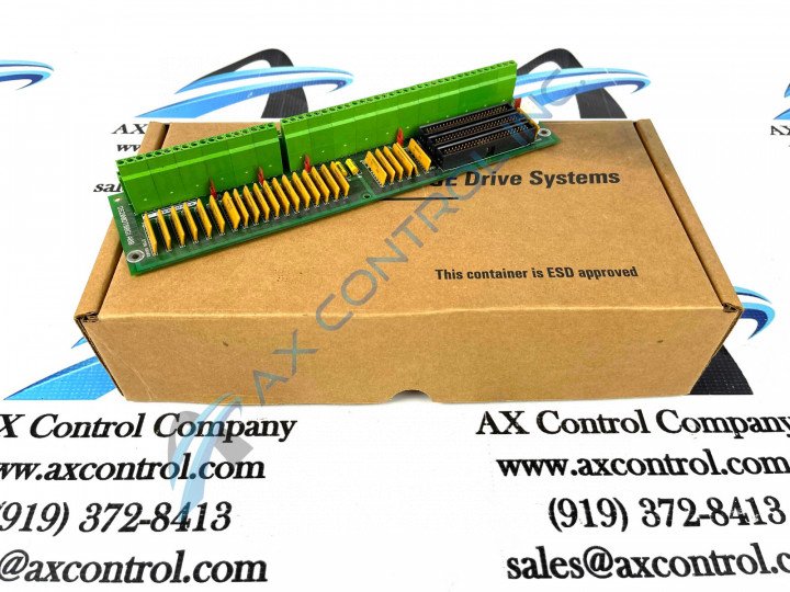
The DS200DTBBG1A Contact Input Expansion Termination Module was made for General Electric's Mark V Turbine Control System Series.

AVAILABILITY:

IN STOCK
SHIPS TODAY

Sell Surplus: Have a DS200DTBBG1A to sell? Sell Now
Exchange Credit: Learn more about our exchange credit program
  • Part Number: DS200DTBBG1A
  • SKU: DS200DTBBG1AGBTC
  • Manufacturer: GE Boards & Turbine Control
  • Series: Mark V DS200

DS200DTBBG1A Technical Specifications

Manufacturer GE General Electric
Series Mark V
Part Number DS200DTBBG1A
Functional Description Terminal Board Digital Connector Card
Functional Acronym DTBB
PCB Coating Normal Coating
Functional Revision 1 A

Product Description

The DS200DTBBGIA Contact Input Expansion Termination Module is an integral part of its Mark V Series of products, as mentioned above. This General Electric PCB or printed circuit board for short features 2 terminal blocks with terminals for 95 signal wires in each. It also contains 3 50-pin connectors. The IDs for the 40-pin connectors are JFF, JFG, and JFH. The DS200DTBBGIA also is populated with bayonet connectors and 5 jumpers. Because the DS200DTBBGIA board has 3 40-pin connectors, it is important to record what 40-pin ribbon cable is connected to which of the connectors. When you restart the drive after replacing the board, it is important to get the drive back in service to regain productivity. If you have connected the ribbon cables to the wrong connectors, it will require you to bring down the drive, move the ribbon cables to the right connectors, and restart the drive. This can lead to a loss of productivity and will inconvenience operators who work on drives that are nearby.

The potential exists to have a maximum of 110 signal wires attached to the terminal blocks of the DS200DTBBGIA Contact Input Expansion Termination Module. This will be difficult to manage without a method to document where the separate signal wires are connected. One terminal block is assigned TB1 as the ID and the other terminal block is assigned TB2 as the ID. The separate terminals are numbered in sequence on each terminal block. So, to identify a specific terminal you use the terminal block ID and the number assign to the terminal. Some examples are TB1 90 and TB2 48. TB1 90 is terminal 90 on terminal block 1, while TB2 48 is terminal 48 on terminal block 2.

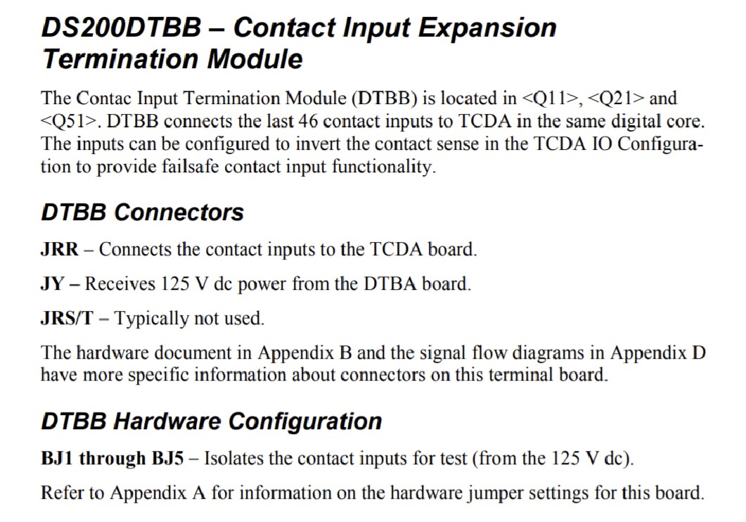
Now that some of the various hardware elements afforded to the assembly of this DS200DTBBGIA Conact Input Expansion Termination Module have been revealed, it is possible to explain the types of connectors compatible with this Mark V Series product. Some of the connector types used in conjunction with this DS200DTBBGIA Contact Input Expansion Termination Module include the JRR TCDA contact input connector, the JY 125 V dc DTBA board power connector, and the JRS/T connector, which is typically unused.

Frequently Asked Questions about DS200DTBBG1A

What digital contacts is DS200DTBBG1A for?
DS200DTBBG1A is the termination for digital contact inputs 47-96. It is recommended for DS200DTBBG1A to bring field contacts back in pair to the correct input terminals on DS200DTBBG1A.
When is an external power supply used with DS200DTBBG1A?
An external power supply must be used with DS200DTBBG1A if DS200DTBBG1A is using 24 VDC inputs. To do this, remove the power connector from the power distribution core and connect 24 VDC to DS200DTBBG1A.
What should I note about solid state field contacts on DS200DTBBG1A?
Make note that solid state field contacts on DS200DTBBG1A may still present a sufficient voltage in an "open" state to cause the DS200DTBBG1A to read the contact as "closed."

Reviews For DS200DTBBG1A

Internal Review
(5.0)

This highly-connected model of General Electric printed circuit board is well-supported by its singular A-rated functional product revision, a necessity given the over one hundred possible terminal connections that can be made to the internal assembly of this product. This Mark V Series Contact Input Expansion Termination Module additionally features several insulated drilled holes for installation purposes, and receives at least a basic level of daily wear and tear protection from its normal-rated style of printed circuit board coating. - AX Control Lead Technician

Repair Services For DS200DTBBG1A

Type Lead Time Price Action
Repair Service 1-2 weeks $415

Our highly skilled technicians can repair your DS200DTBBG1A. All of our repairs come with a 3 Year AX Control Warranty. Please contact us for additional information about our repair process. To receive the repair pricing and lead time listed above please process your repair order via our website. The following repair options may be available upon request:

  • 48-72hr Rush Repair
  • Detailed Repair Reports
  • AX Control Certificate of Warranty

AX Control Warranty Info

All products we sell are backed by our unparalleled warranty. A warranty certificate will be provided with your order upon request.
All PLCs, HMIs, and Turbine Control Boards: 3 Years
All AC/DC and Servo Drives: 2 Years
All Motors: 1 Year
Learn More

DS200DTBBG1A Manuals, White Papers, Data Sheets, and Troubleshooting