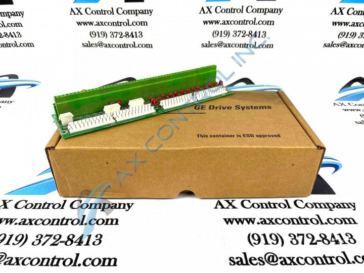
About the DS200DTBCG1AAA
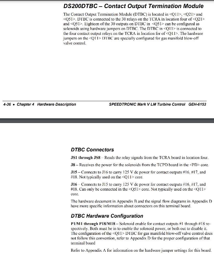
This DS200DTBCG1AAA printed circuit board is an important component product to its greater Mark V Turbine Control System Series and Mark V Series automated drive assembly, as alluded to above. The DS200DTBCG1AAA printed circuit board or PCB posited in this personalized product page is more explicitly-definable as a Contact Output Termination Module, based on this functional description's insertion in relevant Mark V Series and General Electric instructional manual materials. While this DS200DTBCG1AAA product has an official functional description as a Contact Output Termination Module, it may be additionally referenced to as a Connector Relay Terminal Board or simply as a Relay Terminal Board; a less-utilized functional description still accurate for this PCB and included in fringe instructional manuals. This particular DS200DTBCG1AAA printed circuit board product offering its nor considered the original Contact Output Termination Module that was designed and produced as a member of the Mark V Turbine Control System Series; that would be the DS200DTBCG1 Contact Output Termination Module missing this DS200DTBCG1AAA PCB's three significant product revisions.
Hardware Tips and Specifications
As mentioned before, this DS200DTBCG1AAA printed circuit board is referred to in original General Electric and Mark V Series instructional manual materials as both a DS200DTBCG1AAA Connector Relay Terminal Board and as a Contact Output Termination Module. Given this DS200DTBCG1AAA product's dual functionalities, its internal assembly incorporates a unique and elevated amount of hardware components and component specifications. This DS200DTBCG1AAA The GE Connector Relay Terminal Board DS200DTBCGIAAA features 2 terminal blocks with terminals for 110 signal wires in each. It also contains 2 3-plug connectors and 1 2-plug connector and 10 jumpers. Some of the connectors made available to the assembly of this DS200DTBCG1AAA Contact Output Termination Module include:
- The JS1-JS8 TCRA Board Relay Signals Connectors
- The J8 TCPD Board Power Signal Connector
- The J15 and J16 Connected 125 V dc Contact Outputs Power Connectors
All of these aforementioned connector types used in the assembly of this DS200DTBCG1AAA Contact Output Termination Module have been named for their functional application in the assembly of this DS200DTBCG1AAA PCB and its greater Mark V Series assembly and configuration. When you plan to replace the Contact Output Termination Module DS200DTBCGIAAA there are several steps to take before you remove the old board. First it is necessary to remove all power from the drive. Keep in mind that multiple sources of power supply electricity to the drive and when you remove power from 1 source you have to remove power from the remaining sources of power. It is best to consult with someone who is familiar with the installation of the drive to understand the various power sources and how best to remove power to the drive. For example, a rectifier converts ac power to dc power and you can disable a rectifier to remove dc power to the drive. This often is accomplished by removing a fuse from the rectifier. If ac power is supplied to the drive, you might use another method to remove power. This might include pulling a switch or removing power by turning off a circuit breaker. Before making a final purchase decision on this DS200DTBCG1AAA printed circuit board, it is crucial to realize that this DS200DTBCG1AAA product has a full three-fold revision history, which alters its originally-specified performance specifications and dimensions.


