About the DS200DTBDG1A
This DS200DTBDG1A Contact Output Expansion Termination Module, as mentioned above, was manufactured to exist as a member of the Mark V Series of turbine control systems and turbine controls system component products manufactured by respected brand General Electric as a legacy series. The Mark V is considered a legacy series as it is no longer in production by the original GE manufacturer. This DS200DTBDG1A Contact Output Expansion Termination Module's lengthy functional description is reflected in its unique DTBD functional product abbreviation. Before making a final purchase decision on this DS200DTBDG1A Mark V Series printed circuit board, it is crucial to be aware of the fact that this PCB is not the original Contact Output Expansion Termination Module offered for GE's Mark V Series; that would be the DS200DTBDG1 parent printed circuit board without this DS200DTBDG1A PCB's singular functionality-enhancing revision.
Hardware Tips and Specifications
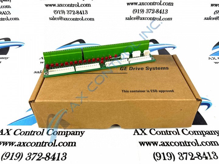
The GE Terminal Board DS200DTBDG1A features 2 terminal blocks. Each block contains 107 terminals for signal wires. The GE Terminal Board DS200DTBDG1A also contains multiple test points, 2 jumpers, and 3 34-pin connectors. The ID of the test points on the board begin with TP and end with a number. TP1 and TP2 are some examples. The IDs are important because the servicer can refer to the written publication that ships with the board from the factory for information about the test points. However, only a trained servicer will have the background, experience and knowledge to test the board. The testing equipment used to test the board must be qualified for the purpose, fully functional, and in good working order. This testing equipment must also be calibrated for the task; in good working condition with probes intended for testing attachment.
While it certainly is important ot be cognizant of safe and normative testing processes for this DS200DTBDG1A Contact Output Expansion Termination Module, it is important too to identify some of the various connectors adopted into the assembly of this Mark V Series product. These connectors include:
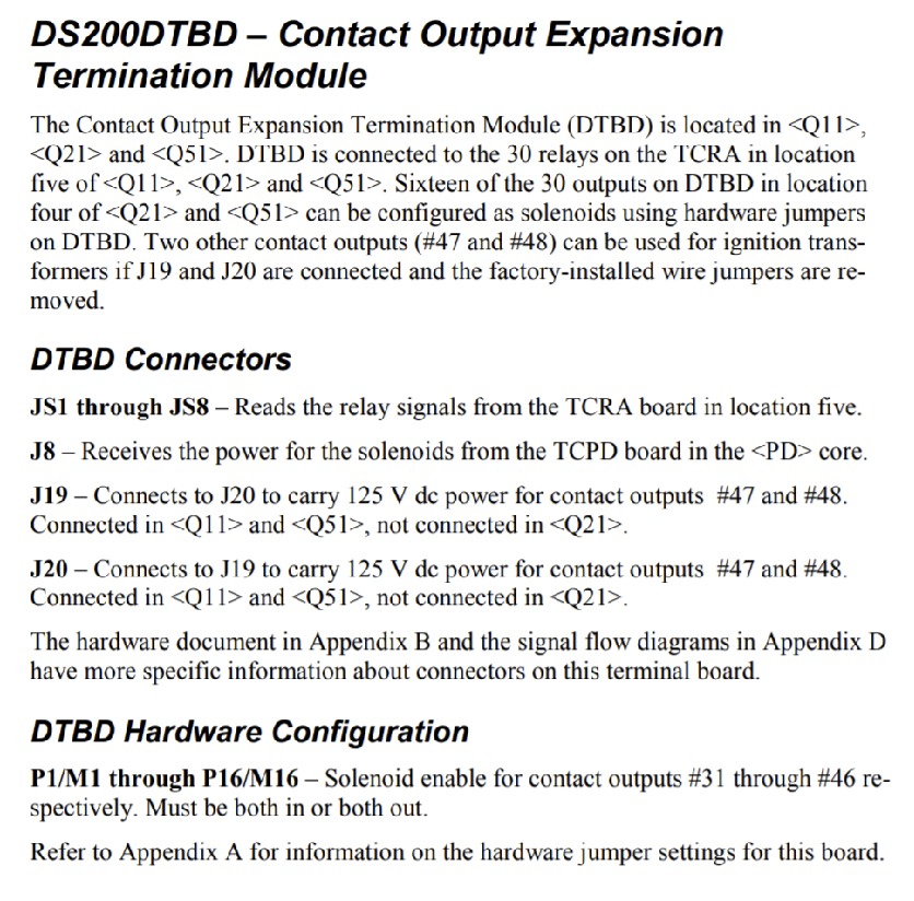
- The J8 TCPD board solenoid power connector
- The J19 125 V dc 47 and 48 contacts output power connector
- The J20 125 V dc 47 and 48 contacts output power connector
In addition to these three stated 34-pin connectors, the assembly of this DS200DTBDG1A Terminal Board introduces a series of eight total other connectors, labeled JS1 through JS8, that read relay signals from the Mark V Series's TCRA board.


