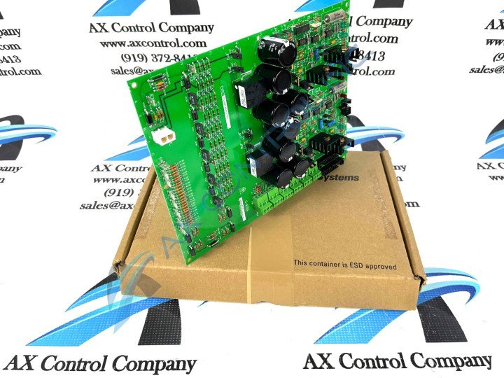
About the DS200EXDEG1AEA
As mentioned before, this DS200EXDEG1AEA De-Excitation Control Board was originally manufactured and distributed for their Mark V Series of turbine control systems. The specific intended functionality of this Mark V Series product is somewhat debatable, as it is both classifiable generally as a Mark V Series Excitation Control Board, and as a Mark V Series De-Excitation Control Board. This DS200EXDEG1AEA printed circuit board is additionally a modified version of a pre-existing Mark V Series product; altering the DS200EXDEG1 parent printed circuit board by including two functional product revisions and a singular artwork-configuratory revision.
Hardware Tips and Specifications
The GE De-Excitation Control Board DS200EXDEG1A features 2 34-pin connectors, 2 10-pin connectors, and 5 indicator LEDs. It is also populated with 8 capacitors, test points, and terminal connectors. The GE De-Excitation Control Board DS200EXDEG1A also is populated with multiple heatsinks. These heatsinks help cool heat-generating components on the board where without the heatsinks, the components might be damaged, or the high heat might lead to premature failure of the entire Mark V Series drive system. The heat sinks require 4 inches of space above the heatsinks for air flow to draw heat away from them. Unfortunately, this necessary clearance limits the positions in the drive interior where the board can be installed. It is best practice to first note where the old board is installed and install the replacement board in the same location. To remove the old board, care is required to perform the task safely due to the weight of the board and the heatsinks that populate it. For safe and normal de-installation, original General Electric instructional manual materials instruct you to use one hand to remove the screws installed in each corner of the board, while using the other hand to support the board.
The DS200EXDEG1AEA De-Excitation Control Board was populated with LEDs that indicate the health of processing functions. If one or more LEDs are not lit, it indicates that an error has occurred or another problem has been encountered. To investigate further you can use the test points to test the specific circuits on the board. The test points each has an ID that is prefixed with TP and ends with a numerical value. TP1, TP3, and TP 6 are samples of test point IDs that you will encounter upon visual inspection of this Mark V Series product.


