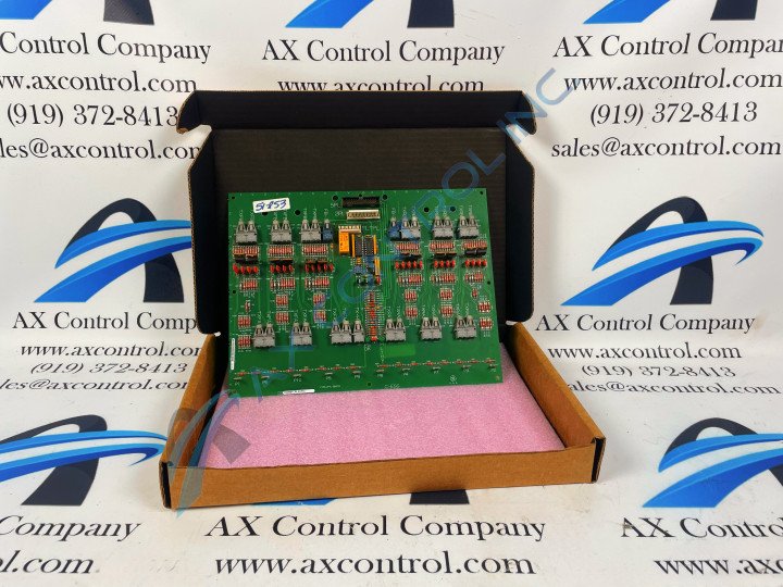
About the DS200FCRLG1
The DS200FCRLG1 printed circuit board featured on this personalized product page is a Mark V Turbine Control Series product originally manufactured by General Electric, as posited above. The Mark V Series is a relatively-new product series from General Electric, that incorporates some of the standard Speedtronic technology GE has been designing for turbine control systems since the Mark I Series put out in the later 1960s. This DS200FCRLG1 printed circuit board or PCB for short exists as the original product with its intended functionality created for the Mark V Series, as its possesses both a normal assembly type and an assembly that has not been edited through the attachment of any relevant product revisions. This DS200FCRLG1 PCB is specifically definable as a Firing Circuit Control Board, its original functional product description that appears in many relevant General Electric and Mark V Series instructional manual materials.
Hardware Tips and Specifications
This DS200FCRLG1 Firing Circuit Control Board is a printed circuit board developed for General Electric's Mark V Series of turbine control systems, and as such, necessitates the inclusion of its own particular set of hardware component inclusions and specifications. The GE Firing Circuit Control Board DS200FCRLG1 features 27 bayonet-type connectors. It is also populated with 27 jumpers, 1 34-pin connector, and 1 9-pin connector. The GE Firing Circuit Control Board DS200FCRLG1 is one component in a complex drive assembly. Many of the components in the drive are heat producing. The electrical components embedded on boards such as this DS200FCRLG1 PCB produce heat and so do the moving parts, including the powerful electrical motor. To enable the DS200FCRLG1 board to work effectively and without error, the drive must be installed in a location that is cool or room temperature. To select a location for the installation, choose a space for the drive with at least 18 inches between the drive and other equipment. The DS200FCRLG1 PCB and related drive need a constant supply of cool air to circulate through it and keep the components below a threshold. If the installation space has heat-generating equipment in it, you might need to install fans to help cool the drive, to avoid risking an overtemperature drive fault.
While it is certainly useful to understand this DS200FCRLG1 Firing Circuit Control Board's normative installation procedures, it is also crucial to understand many of the basic hardware component choices and allegiances revealed in the DS200FCRLG1 functional product number itself. Beginning with the dual-functional DS200 series tag, this DS200FCRLG1 alphanumeric product number reveals relevant details including this DS200FCRLG1 printed circuit board's normal Mark V Series assembly version, its domestic location of original manufacture, its FCRL functional product acronym, its normal style of PCB protective coating, and its group one Mark V Series product grouping. The normal style of PCB or printed circuit board protective coating applied to the base circuit board of this DS200FCRLG1 PCB exists as a thick rudimentary daily wear and tear and insulated protective layer that is extended to individual hardware elements on this DS200FCRLG1 PCB's base circuit board on a functional priority basis.


