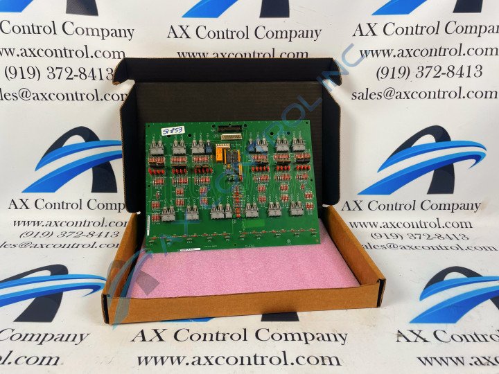
About the DS200FCRLG1A
This DS200FCRLG1A printed circuit board was originally manufactured for placement in General Electric's Mark V Turbine Control System Series, as mentioned above. This DS200FCRLG1A PCB's Mark V Series, as indicated by its full extended series name, has specific applications in the control and management systems of compatible steam, wind, and gas turbine automated drive assemblies, and is considered a General Electric legacy series as its manufacture has been discontinued in the years since its initial release. This DS200FCRLG1A printed circuit board or PCB for short's Mark V Turbine Control System Series, while definable as a legacy series, also exists as one of the final General Electric product series to make use of the retailer's patented Speedtronic control system technology first introduced alongside the rollout of the Mark I. This DS200FCRLG1A printed circuit board is more accurately-definable as a Firing Circuit Control Board; its official functional product description as revealed in Mark V Series instructional manual materials. While this DS200FCRLG1A PCB is definable functionally as a Firing Circuit Control Board, the original product with that specific role within the Mark V Turbine Control System Series is the DS200FCRLG1 parent printed circuit board missing this DS200FCRLG1A offering's A-rated functional product revision.
Hardware Tips and Specifications
This DS200FCRLG1A printed circuit board necessitates its own specific series of Firing Circuit Control Board functionality-introducing hardware components and component specifications. The GE Firing Circuit Control Board DS200FCRLG1A features 27 bayonet-type connectors. It is also populated with 27 jumpers, 1 34-pin connector, and 1 9-pin connector. The 27 bayonet connectors are connected to matching pins that are attached to the ends of the signal and power cables. Given this DS200FCRLG1A product offering's attribution to a General Electric legacy series, it should come as no real surprise that its originally-printed instructional documentation has largely been made unavailable in terms of our internet research purposes. With this being true, the DS200FCRLG1A functional product number can be considered a strong source of original DS200FCRLG1A board hardware component and component specification information, revealing this DS200FCRLG1A PCB's:
- Normal Mark V Series assembly type
- Domestic location of original manufacture
- FCRL functional product acronym
- Normal style of PCB surface coating
- Group one Mark V Series grouping
- A-rated functional product revision
The cables in this DS200FCRLG1A PCB's assembly are also connected to other devices and boards in the drive. To install a cable in the bayonet connector, align the pin with the connector and press it into place. Press the cable until it is firmly connected and it clicks into place. To disconnect a cable from the bayonet connector, hold it by the connector at the end of the cable and pull it out of the connector. Do not tug the cable out by holding the cable. This might cause the signal wires to dislodge from the connector end. With multiple wires, cables, and ribbon cables connected to the board, you must consider proper cable routing. One consideration is that the signal wires must be routed separately from the power cables. The power cables radiate interference that can make the signals carried to and from the board useless. Route the signal wires as far away from the power cables as possible. Or, limit the space the signal and power cables are routed near each other. The more current that the power cables carry, the shorter the distance should be that the signal and power cables are routed together. In some circumstances, you can use shielded cables to protect the signals from the power cables.


