About the DS200FCRLG1AFC
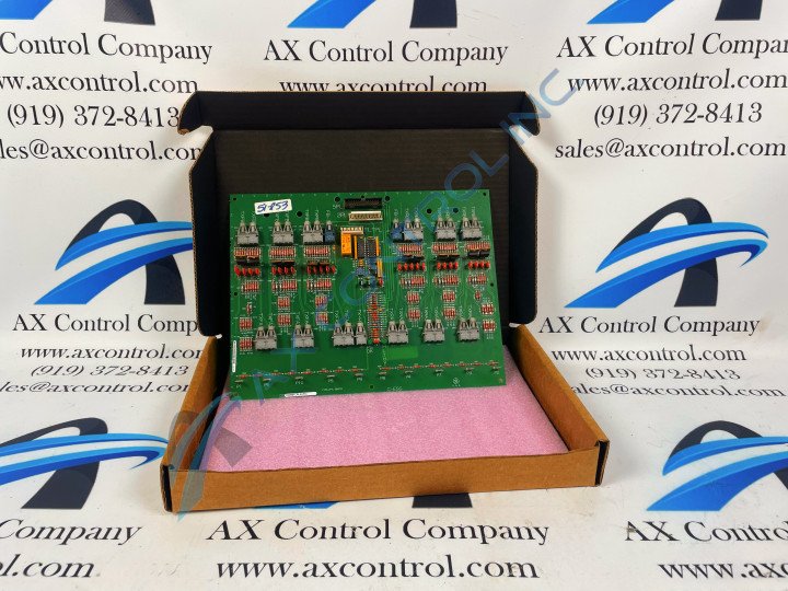
This DS200FCRLG1AFC printed circuit board product offering was originally manufactured for use in General Electric's Mark V Turbine Control System Series. As you can probably tell by its full extended series name, the Mark V Series that this DS200FCRLG1AFC device has specific applications in the control and management systems of wind, steam, and gas turbine automated drive assemblies, and is considered a General Electric legacy series due to its original manufacturer's discontinuation of DS200FCRLG1AFC product production. While a legacy series, this DS200FCRLG1AFC printed circuit board or PCB for short's Mark V Turbine Control System Series is also identifiable as one of the final General Electric product series to incorporate the patented Speedtronic control system technology into its various offerings. This DS200FCRLG1AFC printed circuit board product offering is truly better-describable as a Firing Circuit Control Board; its official functional product description that it is referred to by in original Mark V Series instructional manual materials. This DS200FCRLG1AFC printed circuit board is not the original product of its functionality manufactured for the Mark V, however; that would be the DS200FCRLG1 Firing Circuit Control Board notably missing all three of this DS200FCRLG1AFC PCB's significant product revisions.
Hardware Tips and Specifications
As with any General Electric printed circuit board available in our stock of new and reconditioned products, this DS200FCRLG1AFC offering makes use of its own particular set of functionality-introducing hardware components and component specifications. The GE Firing Circuit Control Board DS200FCRLG1AFC features 27 bayonet-type connectors. It is also populated with 27 jumpers, 1 34-pin connector, and 1 9-pin connector. The jumpers on the GE Firing Circuit Control Board DS200FCRLG1AFC configure the firing signals transmitted from the connectors. For that reason they are important and you must consider them when you replace the board. Each jumper can cover 2 of 3 jumpers on the board. The jumper can cover pins 1 and 2 or pins 2 and 3. Depending on which pins are covered the behavior of the board is changed. When the board from the factory is shipped, the package includes an installation guide with a description of each of the jumpers. It describes how the configuration changes if pins 1 and 2 are covered or if pins 2 and 3 are covered. The jumpers are identified on the board with the two letter ID, JP followed by a number. Some examples of jumper IDs are JP1, JP4, and JP9. The installer will confer with the engineers and operators to determine how the drive should be configured to best meet the needs of the site. Once configuration is complete, the drive will perform as needed during normal processing. To replace the drive, one step is to review the jumper settings on the old board and move the jumpers on the replacement board to match. Some of the jumpers will remain in the default positions, which are the positions in which the jumper arrives from the factory. They are often the most common settings.
The above DS200FCRLG1AFC specific jumper information represents this DS200FCRLG1AFC product's jumpers' disproportionate mentioning in the very sparse DS200FCRLG1AFC instructional manual materials available for internet research. With this being said, the DS200FCRLG1AFC functional product number itself can be considered a great source of original DS200FCRLG1AFC hardware information, starting with the beginning dual-functional DS200 series tag. This series tag outlines the DS200FCRLG1AFC board's status as a domestically-manufactured General Electric product with a normal Mark V Series assembly type. This DS200FCRLG1AFC number's DS200 Series tag is followed by individual naming components detailing this DS200FCRLG1AFC product's:
- FCRL functional product abbreviation
- Normal style of PCB coating
- Group one Mark V Series grouping
- A-rated primary functional revision
- F-rated secondary functional revision
- C-rated artwork configuration revision


