About the DS200FSAAG1
This DS200FSAAG1 printed circuit board product offering was originally manufactured by General Electric as mentioned before, specifically for placement in their now-obsolete Mark V Turbine Control System Series. The Mark V Turbine Control System Series that this DS200FSAAG1 printed circuit board or PCB for short belongs to is obsolete as its exists as a defunct Mark V Legacy Series due to its eventual manufacturing discontinuation that took place in the many years following its initial release. As you may have been able to guess from its full extended series name, this DS200FSAAG1 PCB and the rest of its Mark V Series has specific applications in the control and management systems of popular and compatible wind, steam, and gas turbine automated drive assemblies. While this DS200FSAAG1 PCB's greater Mark V Series has to be classified as a now-obsolete legacy product series, it is still well-updated in one respect as it exists as one of the final General Electric product series to utilize the patented Speedtronic control system technology first seen alongside the release of the Mark I Series in the late 1960s. This DS200FSAAG1 printed circuit board product offering is the original product of its intended Mark V Turbine Control System Series functionality; existing as the original Field Supply Amplifer Board as evidenced by its DS200FSAAG1 functional product number's lack of any trailing revision-indicating digits.
Hardware Tips and Specifications
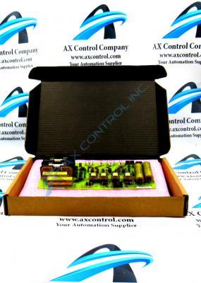
The GE Field Supply Amplifier Board DS200FSAAG1 features 5 jumpers, one 10-pin connector, and two fuses. It is also populated with multiple test points. The GE Field Supply Amplifier Board DS200FSAAG1 has four holes that enable you to mount it on the standoffs on another device. Align the four holes on the board with the standoffs and use screws to attach the board. Once attached, you cable the board to the device and the drive component work together. There are only 4 capacitors on the DS200FSAAG1 board. Two of the capacitors on DS200FSAAG1 are located on the right-hand side of the board. The other two capacitors on the board are located on the left-hand side. The capacitors store high voltage and also release it during normal operation of the board. As this DS200FSAAG1 Field Supply Gate Amplifier Board is not available in stored Mark V Series research manual materials available online given its now-obsolete Mark V Legacy product series status, the DS200FSAAG1 functional product number itself can be considered a primary source of DS200FSAAG1 Board hardware component and component specification information. The DS200FSAAG1 functional product number reveals a number of DS200FSAAG1 Board details in a series of functional naming chunks. For example, the DS200FSAAG1 functional product number begins with the dual-functional DS200 series tag delegating this DS200FSAAG1 PCB's normal Mark V Series assembly as well as its domestic location of original manufacture. Some of the other critical hardware details embedded in the DS200FSAAG1 functional product number include this DS200FSAAG1 PCB's:
- FSAA functional product acronym
- Normal PCB coating style
- Group one Mark V Series product grouping
- Lack of any product revisions
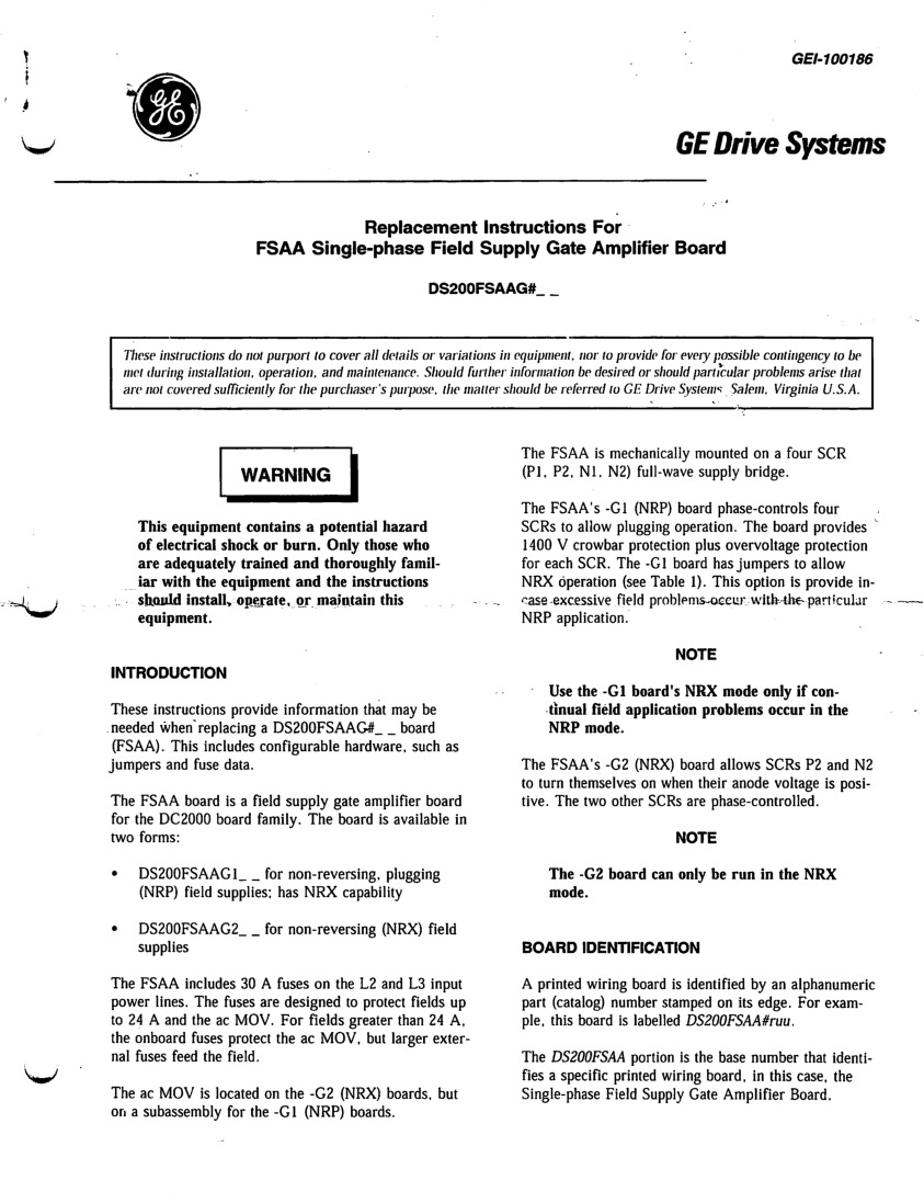
The DS200FSAAG1 board also is populated with five jumpers. The jumpers in the assembly of this DS200FSAAG1 PCB are classified as manually-moveable Berg-type jumpers, the most common style of Mark V Series customizable hardware available to its various products. As identified in the DS200FSAAG1 original instructional manual attached above in the manuals tab, these jumpers are supplied to give the DS200FSAAG1 PCB a non-reversing field supply or NRX option. Some of the jumpers are only used during the manufacturing process to test various signals and circuits in the board. And the jumpers cannot be moved by the servicer because the alternate position is not a supported configuration. However, other jumpers can be used to configure the board by changing the functionality of the board. To read a description of the jumpers on the board, review the product information that was supplied with the original board from the manufacturer. Consider that when you are replacing a defective board, to obtain the same functionality in the replacement board, position the jumpers on the replacement board to match the positions on the defective board.


