About the DS200FSAAG1A
This DS200FSAAG1A printed circuit board is a General Electric product originally designed and manufactured for the Mark V Turbine Control System Legacy Series. The Mark V Series that this DS200FSAAG1A printed circuit board or PCB for short belongs to is characterizable as a legacy series due to its manufacturing discontinuation in the years following its initial release. While this DS200FSAAG1A product offering's greater Mark V Series is a legacy series, it is also characterizable as one of the final General Electric Mark product series to make use of the retailer's patented and esteemed Speedtronic control system technology first released in the late 1960s. This DS200FSAAG1A PCB is better definable as a Single-phase Field Supply Gate Amplifier Board, although the original product of this functionality to exist within the Mark V Series is the DS200FSAAG1 parent printed circuit board of the same functionality.
Hardware Tips and Specifications
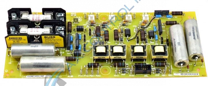
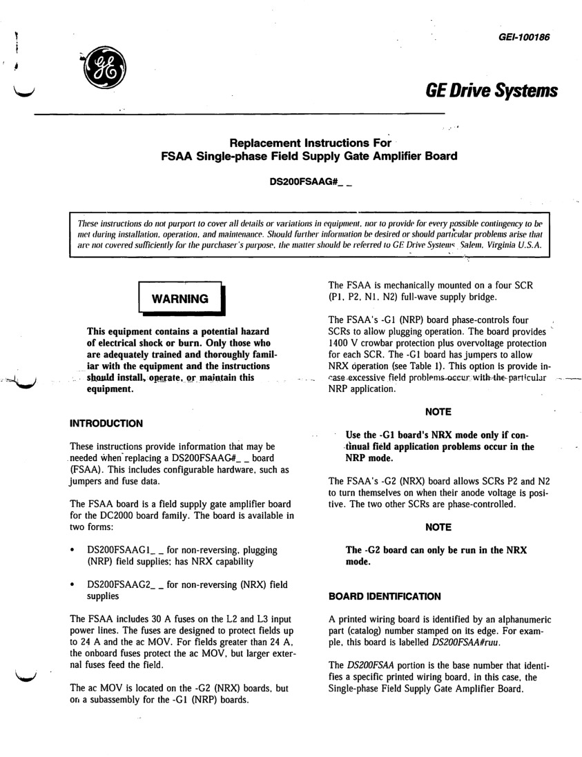
This DS200FSAAG1A PCB, like any Mark V Series product available here, utilizes a unique set of hardware components and component specifications to achieve full functional status within its greater Mark V Series automated drive assembly. The GE Field Supply Amplifier Board DS200FSAAG1A features five jumpers, one 10-pin connector, and two fuses. It is also populated with multiple test points. The GE Field Supply Amplifier Board DS200FSAAG1A is designed to attach to another drive component; standoffs on the other component enable the board to be secured with screws. The holes on each corner of the DS200FSAAG1A board align with the standoffs and enable you to insert the screws through the board. When you tighten the screws use care to avoid damaging the board by over-tightening the screws. The area surrounding the holes on the board has a metal surface which helps protect the board. The two fuses in the assembly of this DS200FSAAG1A product offering, as described in the DS200FSAAG1A instructional manual attached above, exist as 30 A, 60 V fast-acting types of fuses. Before making any final purchase decision on this DS200FSAAG1A product, it is of paramount importance to understand that this DS200FSAAG1A device's originally-introduced performance specifications and dimensions have been altered through its acceptance of an A-rated functional product revision.
Examine how the jumpers are positioned on the previous DS200FSAAG1A board and duplicate the positions on the newly installed board. In this way, the new board will behave the same as the hardware positions of the previous board. Align the new board over the standoffs and tighten the screws with a screwdriver. Use two hands to tighten the screws, and use one hand to guide the screwdriver into the screw head, and the other to turn the screw. Make sure all four screws are evenly tightened in the standoffs. There are two groups of FSAA boards, one is associated with the DS200FSAAG1A model, and the other is labeled as DS200FSAAG2. Both are non-reversing and are associated with field supplies, but the DS200FSAAG2 group is only used with non-reversing field supplies, while the DS200FSAAG1 group is used with non-reversing plugging field supplies but does have the capacity to work in a DS200FSAAG2 or NRX setting.


