❮


❯


DS200FSAAG2ABA
- 4.93 (15)
- Click a star to rate this product
- 4.93 (15)
- Click a star to rate this product
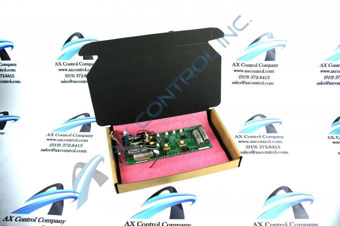
The DS200FSAAG2ABA Field Supply Gate Amplifier Board was manufactured for General Electric's Mark V Turbine Control System Series.
AVAILABILITY:
IN STOCK
SHIPS IN 3-5 DAYS
- Part Number: DS200FSAAG2ABA
- SKU: DS200FSAAG2ABAGBTC
- Manufacturer: GE Boards & Turbine Control
- Series: Mark V DS200
DS200FSAAG2ABA Technical Specifications
| OEM | GE General Electric |
| Product Series | Mark V |
| Functional Part Number | DS200FSAAG2ABA |
| Functional Product Description | Field Supply Amplifier Board |
| Functional Acronym | FSAA |
| PCB Coating | Normal Coating |
| 1st Functional Revision | A |
| 2nd Functional Revision | B |
| Artwork Revision | A |
About the DS200FSAAG2ABA
This DS200FSAAG2ABA printed circuit board product offering was originally designed and manufactured for General Electric's Mark V Turbine Control System Series, as mentioned earlier. This DS200FSAAG2ABA PCB was developed to exist within the specific Mark V Series functional role as a Field Supply Gate Amplifier Board, although the original product of this specific Mark V Series functionality is the DS200FSAAG2A parent Field Supply Gate Amplifer Board missing all three of this DS200FSAAG2ABA device's three significant product revisions. As you may have been able to guess through analysis of its full extended series name, this DS200FSAAG2ABA printed circuit board or PCB for short's greater Mark V Series has specific applications in the management and control systems of compatible and popular wind, steam, and gas turbine automated drive assemblies. This DS200FSAAG2ABA product offering's greater Mark V Series has to be considered a now-obsolete General Electric legacy product series, as its manufacture has been discontinued due to obsolescence in the many years following its initial GE release. This DS200FSAAG2ABA PCB's Mark V Series, while a legacy product series, is still somewhat well-updated, as it is one of the final General Electric product series to make use of the Speedtronic control system technology first introduced with the rollout of the Mark I Series in the late 1960s.
Hardware Tips and Specifications
As with any Mark V Series product offering made available to our new and reconditioned inventory here, this DS200FSAAG2ABA PCB's functionality is introduced with its internal assembly's acceptance of a specific series of functionality-enhancing hardware components. The GE Field Supply Amplifier Board DS200FSAAG2ABA features 5 jumpers, one 10-pin connector, and two fuses. It is also populated with multiple test points. Along with the 10-pin connector, the GE Field Supply Amplifier Board DS200FSAAG2ABA also is populated with four 2-pin connectors and so the board can be connected to multiple cables that must be disconnected and reconnected during the replacement. Luckily enough for the sakes of this DS200FSAAG2ABA product offering's personalized product page here, many of the aforementioned different styles of customizable hardware pieces in its normal Mark V Series assembly have been named in the DS200FSAAG2ABA original instructional manual attached above in the manuals tab for your convenience. As with any individual hardware components available to the assembly of this DS200FSAAG2ABA product, each of these pieces of hardware is accompanied by their own factory-printed nomenclature label. Some of this DS200FSAAG2ABA printed circuit board's customizable hardware includes:
- Two 30 A, 60 V fast-acting fuses
- Six total JP1-JP6-labeled Berg-type manually-moveable hardware jumpers
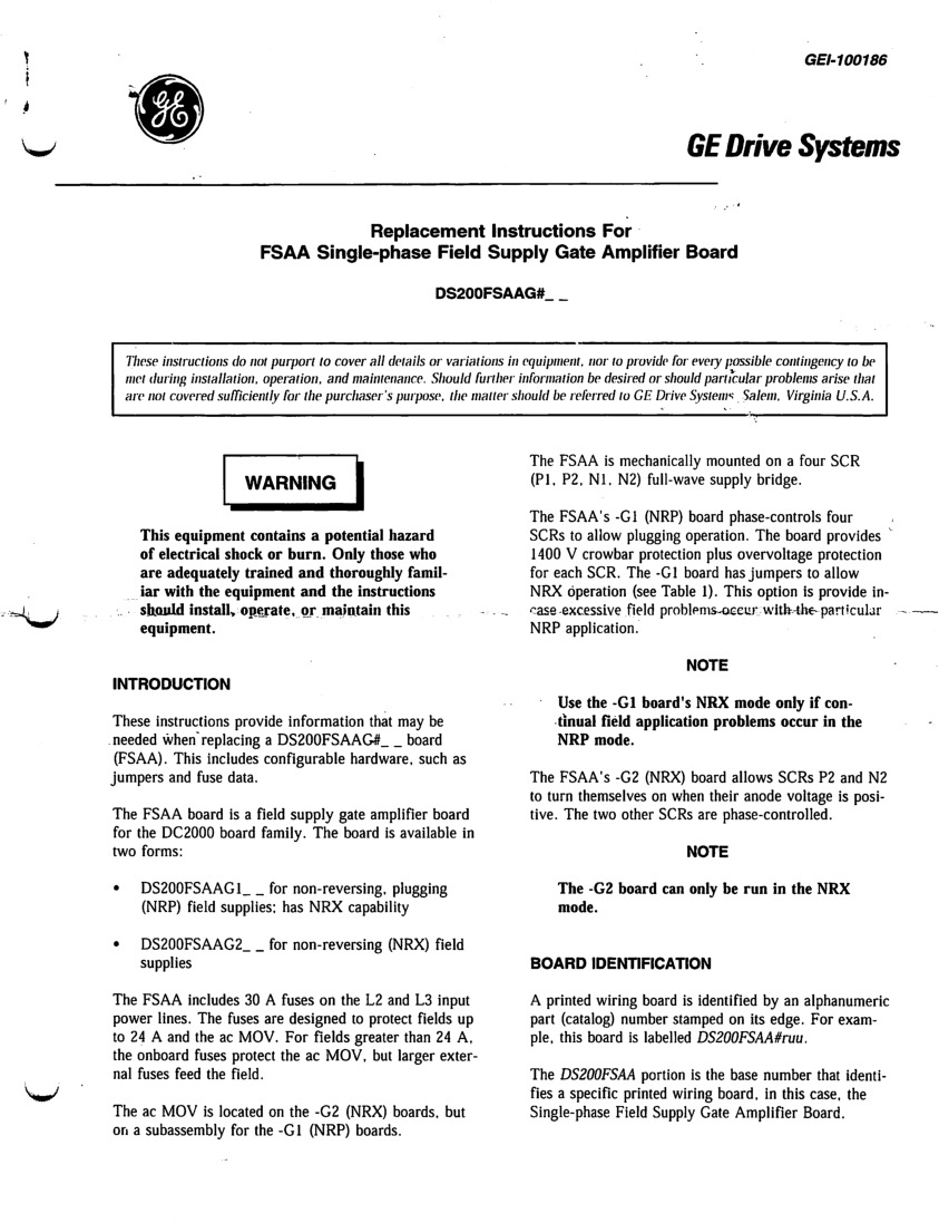
The jumpers in the assembly of this DS200FSAAG2ABA product offering have been factory-set to support the standard NRP default mode, although they are available to select for the NRP mode. This DS200FSAAG2ABA PCB's two total fuses are considered customizable as they can be mounted or dismounted with ease from this DS200FSAAG2ABA printed circuit board's manual-identified onboard fuse block. To avoid costly errors that might lead to increased downtime for the drive, and to make the replacement fast and easy, write on lengths of tape the identifier for the connector to which the cable is connected. Then, attach the tape to the cables. Only then should you disconnect the cables from the board. When you are ready to reconnect the cables, locate the connectors using the identifier and reconnect the cables. When you are disconnecting the cables follow some guidelines to prevent damage. Only grasp the cables by the connector end to remove it. If you pull from the cable portion it puts stress on the cable and might damage the cable by pulling out the wires. This is especially true of ribbon cables because the multiple wires are very fine and the connection from the ribbon to the connector is not well supported. When you reconnect them make sure the cables are fully seated in the connector so that all signals are able to pass through to the board. If a connector has retention clips to hold the board in place, make sure they are engaged. Given the fact that this DS3800HFPC1L1H product here belongs to a now-obsolete legacy product series, it is not accompanied by any great amount of originally-pertinent instructional manual materials online, which means that the DS3800HFPC1L1H functional product number itself can be regarded as a decently strong source of DS3800HFPC1L1H Board hardware component and component specification information, as it codes for these various details through a series of General Electric-formulated functional naming segments. For starters, this DS3800HFPC1L1H functional product number exposes the DS3800HFPC1L1H PCB's normal Mark IV Series assembly version as well as its domestic location of original GE manufacture.
Frequently Asked Questions about DS200FSAAG2ABA
What kind of batteries does DS200FSAAG2ABA have?
How big is DS200FSAAG2ABA?
What kind of fuses does DS200FSAAG2ABA have?
Reviews For DS200FSAAG2ABA
Internal Review
(5.0)This DS200FSAAG2ABA Field Supply Gate Amplifier Board is a General Electric Mark V Turbine Control System Series PCB that deals with a lot of high voltages, given its specific intended gate functionality. With this in mind, this Mark V Series group 2 product is well-insulated, boasting a thick normal style of PCB coating, a set of Mark V Series-standardized voltage-limiting hardware components such as rectifiers, capacitors and diodes, and finally a full, three-fold personal product revision history adding additional voltage protections. - AX Control Lead Technician
Repair Services For DS200FSAAG2ABA
| Type | Lead Time | Price | Action |
|---|---|---|---|
| Repair Service | 1-2 weeks | $1155 |
Our highly skilled technicians can repair your DS200FSAAG2ABA. All of our repairs come with a 3 Year AX Control Warranty. Please contact us for additional information about our repair process. To receive the repair pricing and lead time listed above please process your repair order via our website. The following repair options may be available upon request:
- 48-72hr Rush Repair
- Detailed Repair Reports
- AX Control Certificate of Warranty
AX Control Warranty Info
All products we sell are backed by our unparalleled warranty. A warranty certificate will be provided with your order upon request.
| All PLCs, HMIs, and Turbine Control Boards: | 3 Years |
| All AC/DC and Servo Drives: | 2 Years |
| All Motors: | 1 Year |


