In Stock
DS200GDPAG1AKF Image One
3 year warranty

DS200GDPAG1AKF Image 1
DS200GDPAG1AKF Image 2
DS200GDPAG1AKF Image 3
DS200GDPAG1AKF Image 4

DS200GDPAG1AKF

    Varying star amount pictures Varying star amount pictures Varying star amount pictures Varying star amount pictures Varying star amount pictures
  • 4.94 (16)
  • Click a star to rate this product
    Varying star amount pictures Varying star amount pictures Varying star amount pictures Varying star amount pictures Varying star amount pictures
  • 4.94 (16)
  • Click a star to rate this product
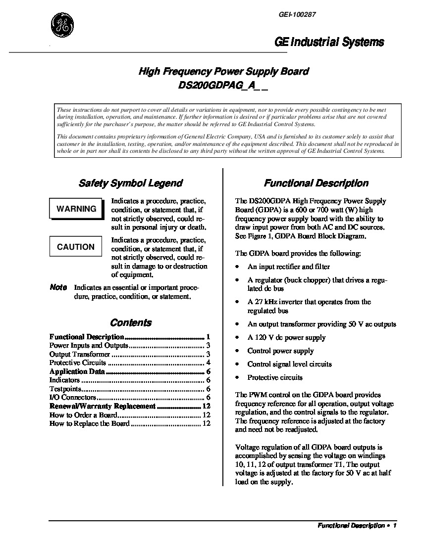
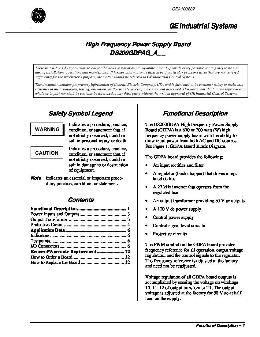
The General Electric DS200GDPAG1AKF High Frequency Power Supply Board was manufactured for the Mark V Series of turbine control systems.

AVAILABILITY:

IN STOCK
SHIPS TODAY

Sell Surplus: Have a DS200GDPAG1AKF to sell? Sell Now
Exchange Credit: Learn more about our exchange credit program
  • Part Number: DS200GDPAG1AKF
  • SKU: DS200GDPAG1AKFGBTC
  • Manufacturer: GE Boards & Turbine Control
  • Series: Mark V DS200

DS200GDPAG1AKF Technical Specifications

Manufacturer GE General Electric
Product Series Mark V
Functional Part Number DS200GDPAG1AKF
Functional Description High Frequency Power Supply Board
Instruction Manual GEI-100287
Functional Acronym GDPA
PCB Coating Style Normal Coating
1st Functional Revision A
2nd Functional Revision K
Artwork Revision F

Product Description

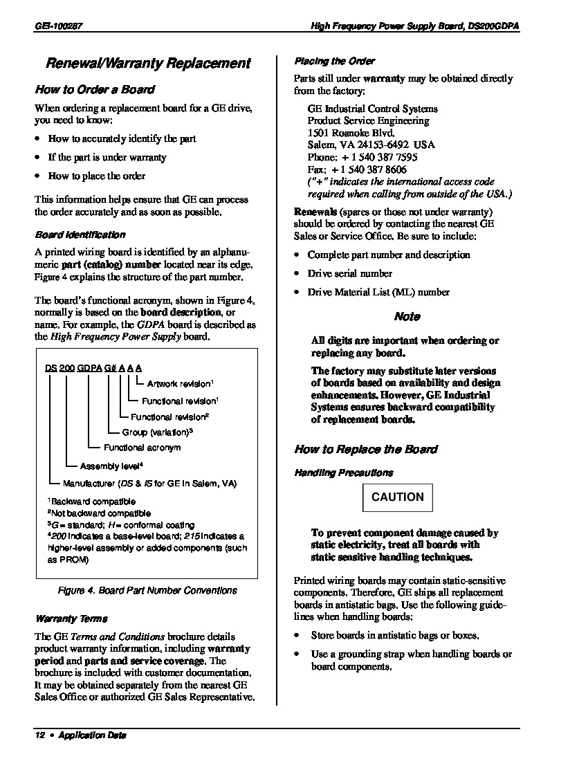
This DS200GDPAG1AKF printed circuit board was originally manufactured for General Electric's Mark V Turbine Control System Series, as explained previously. The Mark V Series that this DS200GDPAG1AKF PCB was originally designed for, as mentioned above, has specific applications in the management and control systems of popular wind, steam, and gas turbine automated drive assemblies, and is considered a General Electric legacy series given its eventual manufacturing discontinuation in the years following its initial release. While considered to exist as a General Electric legacy series, the Mark V Series that this DS200GDPAG1AKF PCB belongs to is one of the final General Electric Mark product series to make use of their patented Speedtronic control system technology first introduced with the rollout of the Mark I in the late 1960s. This DS200GDPAG1AKF printed circuit board is better-definable as a High Frequnecy Power Supply Board, the original functional product description appearing in Mark V Series instructional documentation. The original High Frequency Power Supply Board manufactured for the Mark V Series is the DS200GDPAG1 parent printed circuit board missing this DS200GDPAG1AKF PCB's three-fold revision history.

Hardware Tips and Specifications

The General Electric’s Mark V board DS200GDPAG1AKF is a high frequency power supply card. Boards in this family are compatible with a range of GE brand of drives and exciters. When installed, both AC and DC power supplies can be accepted by the drive system. This card can produce wattages ranging from 600 to 700 W. DC inputs sourced to the board can rate between 105 and 140 VDC. Board sourced AC inputs can safely rate between 80 and 132 VAC. A number of workplace applications are available to the DS200GDPAG1AKF. Integrated features include a 50 VAC output transformer, a control power supply, and a 120 VDC power supply. Both protective and control level circuities are found on this particular card. A number of onboard features allow for inputs to be safely and accurately captured and sent out. These include the 27 kHz inverter and the regulator as well as an input filter and an input rectifier. Each input found on this board is isolated, ensuring that some signals will not interfere with others on the board. Board status information is visually represented to users with the two neon and four LED indicators found on board. Three total fuses are made available to the assembly of this DS200GDPAG1AKF product offering for various voltage limitation purposes; each one of these fuses is accompanied by their own factory-printed nomenclature label. The fuses in this DS200GDPAG1AKF device's assembly include:

  • The F1 Major Failure Damage Limitation Fuse
  • The F2 Power Control Cureent Limitation Fuse
  • The F3 T1 Output Functional Fault Limitation Fuse

All three of the fuses available to the assembly of this DS200GDPAG1AKF High Frequency Power Supply Card have been named through a combination of their factory-printed nomenclature labels and general functional application to the DS200GDPAG1AKF device and its greater Mark V Series automated drive assembly. System operation is reliant on users following all provided installation parameters. This will lessen the risk of any user injuries or drive accidents. Proper wiring is paramount in ensure drive safety. A complete instruction manual for wiring and installing DS200GDPAG1AKF is available in the series manual as well as the device datasheet. The board’s manufacturer, General Electric, originally provided technical support. Our sales team at AX Control is happy to help with all of your DS200GDPAG1AKF needs. For prices on this board and other parts and repairs, please contact a member of our trusted team for more information.

Frequently Asked Questions about DS200GDPAG1AKF

Where is the control power supply located on DS200GDPAG1AKF?
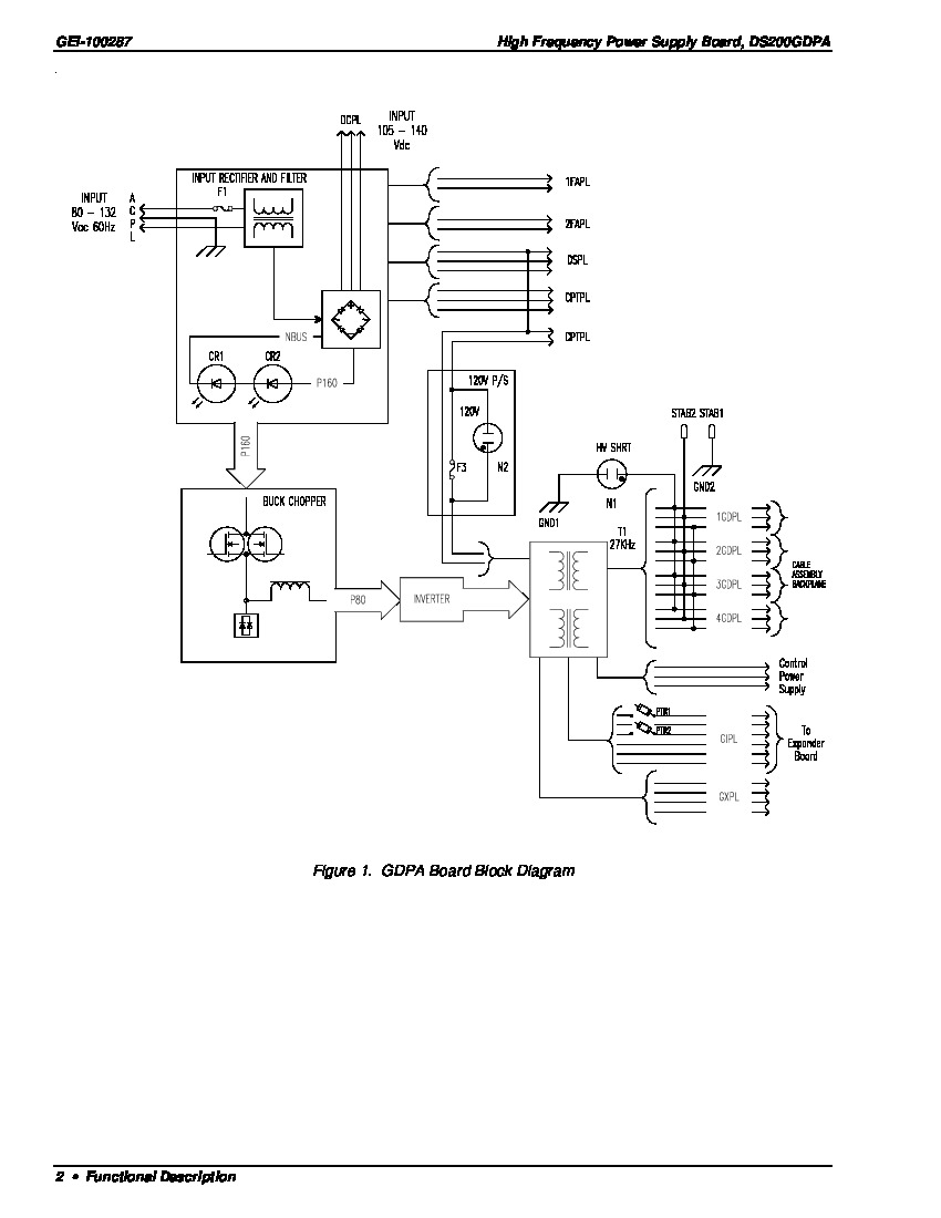
The control power supply for DS200GDPAG1AKF is located in between DS200GDPAG1AKF's connections to the expander board and the cable assembly backplane on DS200GDPAG1AKF. These are all located on the far right bottom of the DS200GDPAG1AKF board. For a visual of where the control power supply on DS200GDPAG1AKF is located, view figure 1 in the manual for DS200GDPAG1AKF - Manual GEI-100287. Figure 1 in the manual is a GDPA Board Block Diagram.
How is DC input routed on DS200GDPAG1AKF?
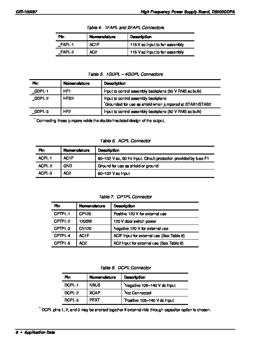
For DS200GDPAG1AKF, DC input is routed from connector DCPL directly to the unregulated DC bus. If a DC source is not used on DS200GDPAG1AKF, optional ride-through capacitence may be connected. DC input for DS200GDPAG1AKF has a range of 105-140 VDC. The voltage range on the unregulated bus connected to DS200GDPAG1AKF is 94-178 VDC.
What happens when an overcurrent signal appears in the inverter?
Because of DS200GDPAG1AKF's protective circuits functions, when an overcurrent signal appears on DS200GDPAG1AKF's inverter, indicating the output of DS200GDPAG1AKF is shorted or overloaded, DS200GDPAG1AKF limits output current by reducing the P80 output rather than tripping the inverter. The overcurrent reference level on DS200GDPAG1AKF is reduced as the voltage on P80 is reduced. Inverter overcurrent and P80 overvoltage are two protective functions the DS200GDPAG1AKF board's protective circuits have.
How do I find the manual for DS200GDPAG1AKF?
We can send you the manual for DS200GDPAG1AKF. We can send you the manual via manual link or manual hard copy. The manual for DS200GDPAG1AKF is Manual GEI-100287 and this manual is the GE Industrial Systems High Frequency Power Board Manual, a specific manual to DS200GDPAG1AKF.

Reviews For DS200GDPAG1AKF

Internal Review
(5.0)

This high-voltage board has multiple test points on its surface. TP testpoints are used for various things, including inverter MOSFET gate signals, analog common, buck pulse width modulation control, and oscillator signal for inverter control. For more information about test points and other components, read through associated manuals and user guides. This DS200GDPAG1AKF PCB is edited through its full three-fold revision history - AX Control Lead Technician

Repair Services For DS200GDPAG1AKF

Type Lead Time Price Action
Repair Service 1-2 weeks $425

Our highly skilled technicians can repair your DS200GDPAG1AKF. All of our repairs come with a 3 Year AX Control Warranty. Please contact us for additional information about our repair process. To receive the repair pricing and lead time listed above please process your repair order via our website. The following repair options may be available upon request:

  • 48-72hr Rush Repair
  • Detailed Repair Reports
  • AX Control Certificate of Warranty

AX Control Warranty Info

All products we sell are backed by our unparalleled warranty. A warranty certificate will be provided with your order upon request.
All PLCs, HMIs, and Turbine Control Boards: 3 Years
All AC/DC and Servo Drives: 2 Years
All Motors: 1 Year
Learn More