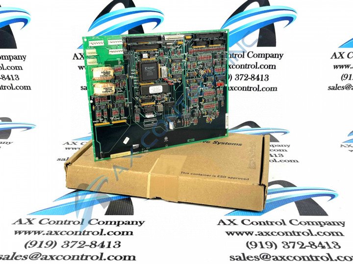
About the DS200GSIAG1A
This DS200GSIAG1A General Electric printed circuit board product offering was originally manufactured for use in the Mark V Turbine Control System Series. The Mark V Series that this DS200GSIAG1A product offering belongs to has specific applications in the control and management systems of compatible wind, steam, and gas turbine automated drive assemblies.
This DS200GSIAG1A printed circuit board or PCB for shorts' Mark V Turbine Control System Series is also one of the final General Electric product series to make use of their patented Speedtronic control system technology first introduced alongside the rolllout of the Mark I Series in the late 1960s.
This DS200GSIAG1A PCB exists functionally as a Common DC Bus Regenerative Board, although the originally-developed product of that functionality within the Mark V Series is considered to be the DS200GSIAG1 parent printed circuit board missing this DS200GSIAG1A product offering's A-rated functional product revision.
Hardware Tips and Specifications
As with any printed circuit board available to General Electric's Mark V Turbine Control System Series, this DS200GSIAG1A product offering makes use of its own specific selection of functionality-introducing hardware component inclusions and specifications. The GE Common DC Bus Regenerative Board DS200GSIAG1A contains three 40-pin connectors, two 16-pin connectors, and 6 jumpers. The board also has 1 8-pin connector, and multiple test points. The 40-pin connectors enable the board to transmit signals to other boards and also receive signals for processing. The connections are made through ribbon cables. Use care when you disconnect the cables because they are prone to having the connection between the connector and the fine wires of the ribbon cable broken. Hold the connector portion of the ribbon cable when you unplug the cable from the board.
While this DS200GSIAG1A printed circuit board's installation and diagnostic testing requirements are pretty well-documented in available original instructional manual materials on the internet, they exist as some of the only DS200GSIAG1A board information available for the purposes of this personalized product page. With that being said, the DS200GSIAG1A functional product number itself is considered a good source of original DS200GSIAG1A board-specific hardware component and specification information, detailing this DS200GSIAG1A product's:
- Normal Mark V Series assembly type
- Domestic location of original manufacture
- GSIA functional product abbreviation
- Normal style of PCB coating
- Group one Mark V Series grouping
- A-rated functional product revision
The test points featured on the base circuit DS200GSIAG1A board are useful for checking the performance of the board if a problem is suspected. The test points can be tested using various testing devices that gauge the signal quality or other factors in the circuit. Make sure the tester is calibrated for the procedure and that the probes are supported for use with the device. A qualified servicer will have the equipment and knowledge required to perform the testing. Also, the qualified tester will know the guidelines and procedures required to work safely around this DS200GSIAG1A PCB's Mark V Series automated drive and components. One guideline is to inspect the area around the drive before starting any work. Any moisture on the floor must be cleaned up and the floor must be dry and clean of oil grease, and other contaminants. If any ungrounded electric cords are present, they must be removed from the area also.


