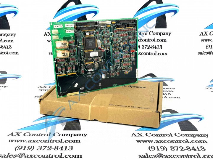
About the DS200GSIAG1ABA
This DS200GSIAG1ABA printed circuit board product offering from General Electric was manufactured for placement specifically in the automated industrial giant's Mark V Turbine Control System Legacy Series, as alluded to previously. As you can probably ascertain from its full extended series name, this DS200GSIAG1ABA PCB's greater Mark V Series has specific applications in the control and management systems of popular and compatible wind, steam, and gas turbine automated drive assemblies. On top of this, the Mark V Series that this DS200GSIAG1ABA printed circuit board or PCB for short belongs to is considered a legacy General Electric product series now obsolete due to an eventual manufacturing discontinuation in the many years following its initial release. Before making any final purchase decision on this DS200GSIAG1ABA PCB, is is crucial to understand that it does not exist as the original General Electric Mark V Series product of its intended functional role; that would be the DS200GSIAG1 parent Common DC Bus Regenerative Board missing this DS200GSIAG1ABA device's three significant product revisions. While this DS200GSIAG1ABA Board's greater Mark V Series is largely outdated due to its legacy series status, it still is updated in at least one respect as it exists as one of the final General Electric product series to incorporate their patented Speedtronic control system technology into its various offerings.
Hardware Tips and Specifications
This DS200GSIAG1ABA product's functionality, as with any Mark V Series product available here, is accessed through the DS200GSIAG1ABA Board's internal assembly's inclusion of a specific series of functionality-inducing hardware components. The GE Common DC Bus Regenerative Board DS200GSIAG1ABA is equipped with various connectors and jumpers, facilitating its seamless integration into the system while offering configuration flexibility. The board features three 40-pin connectors, two 16-pin connectors, and one 8-pin connector, all of which are keyed to ensure proper orientation during cable attachment. The 6 jumpers on the base circuit DS200GSIAG1ABA board allow users to tailor their configuration to suit the processing requirements of their specific site. Refer to the manuals provided by the factory to understand the processing options defined by these jumpers. While some jumpers are solely used during manufacturing, others play a role in defining processing needs. This DS200GSIAG1ABA printed circuit board is not referenced in many originally-printed General Electric manuals online; likely a symptom of its legacy series product classification. With this being true, the DS200GSIAG1ABA functional product number itself can be considered a strong source of DS200GSIAG1ABA Board hardware component and component specification information; coding for specific DS200GSIAG1ABA Board hardware elements in a series of functional naming chunks. For example, the DS200GSIAG1ABA functional product number begins with the DS200 series tag dictating this DS200GSIAG1ABA PCB's normal Mark V Series assembly as well as its domestic original manufacture location. Some of the other relevant DS200GSIAG1ABA Board details revealed through the DS200GSIAG1ABA functional product number include this PCB's:
- GSIA functional product abbreviation
- Normal PCB protective coating style
- Group one Mark V Series product grouping
- A-rated primary functional revision
- B-rated secondary functional revision
- A-rated artwork configuration revision
When dealing with ribbon cables, caution must be exercised, as they are susceptible to damage. To disconnect a ribbon cable, firmly hold the plastic connector with one hand while keeping the board stable with the other hand. Gently pull the ribbon cable out from the board connector to avoid putting stress on the connector and prevent damage to the delicate wires. The DS200GSIAG1ABA model differs from the DS200GSIAG1CHD in several aspects. Firstly, the CHD model possesses an additional jumper located at JP7, providing more configuration options compared to the ABA model. This extra jumper allows for greater flexibility in tailoring the CHD model to specific processing requirements. Furthermore, the CHD model incorporates a Programming EEPROM at location U5, enabling efficient programming and storage of critical data for the device. On the other hand, the older ABA model lacks this feature, potentially requiring alternative methods for programming and configuration. In terms of components, the DS200GSIAG1ABA model exhibits a notable difference in terms of capacitor arrays. The ABA model has fewer capacitor arrays compared to the CHD model. These capacitor arrays are vital for energy storage and voltage stabilization, making the CHD more suitable for applications demanding higher capacitance levels and improved performance.


