About the DS200IIBDG1ADA
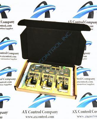
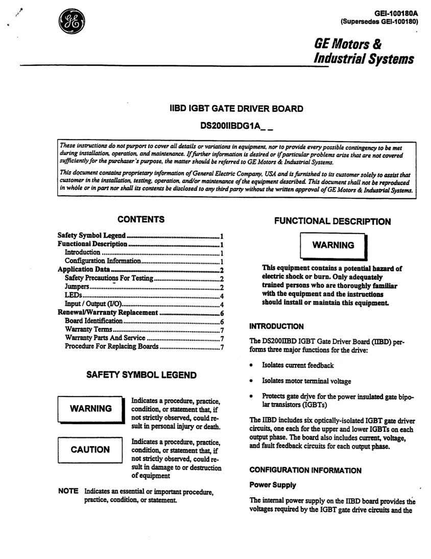
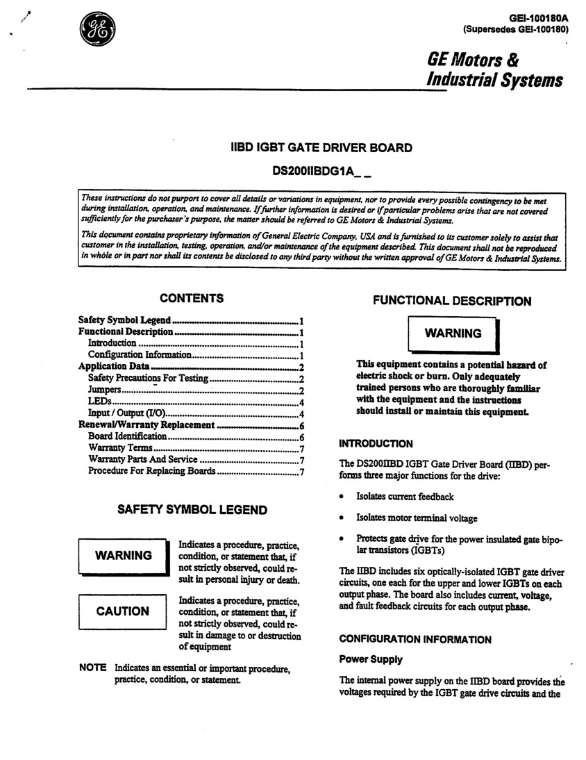
Oftentimes referred to by its functional acronym IIBD, the DS200IIBDG1ADA is a Insulated Gate Bipolar Transistor (IGBT) Board. The DS200IIBDG1ADA has three major functions in terms of the greater overall drive assembly, including current feedback isolation, isolating motor terminal voltage, and protecting the assembly's gate drive for power insulated gate bipolar transistors or IGBTs. This product exists as a member of GE Industrial Systems' Mark V series of automated drive component parts. Please note that while any information provided here may not be completely accurate, as the dimensions of this PCB component part may be influenced by its three revisions.
Hardware Tips and Specifications
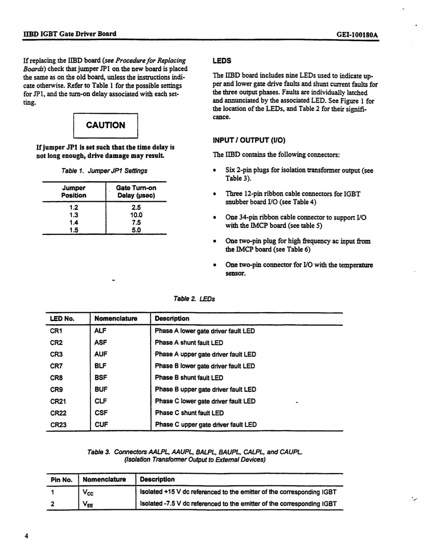
As with any printed circuit board, GE Industry Systems or otherwise, it is important to consider compatibilities and specifications before making a purchase decision. This printed circuit board is unique in a number of components, beginning with DS200IIBDG1ADA's nine indicator LEDs that provide a status of the processing of the board. The LEDs are visible from the interior of the circuit board cabinet and display different colors when lit, demonstrating different drive assembly conditions. Beyond the LEDs that come standard with this PCB, the DS200IIBDG1ADA has a collection of contrasting connectors contributing carefully to customizability and compatibility. Some of these connector types include:
- Six two-pin plugs intended for use in isolation transformer output
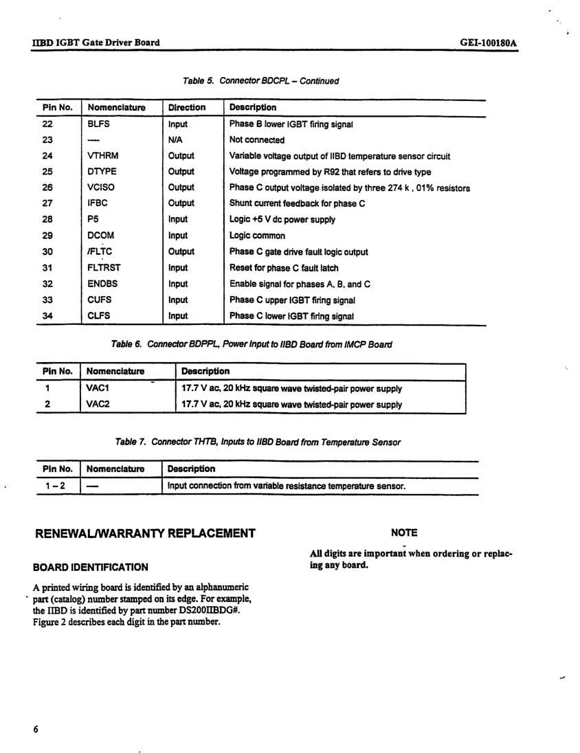
- three ribbon cable connectors for the IGBT snubber board, each with twelve pins
- a singular input/ouput supporting ribbon cable with 34 pins
- a plug for an IMCP boards' high frequency AC input with two pins
- another two-pin connector for the input/output of the assembly's temperature sensor
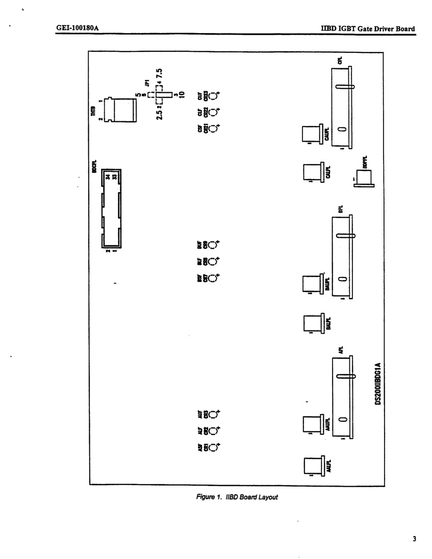
Beyond the various connectors present on the base plate of the DS200IIBDG1ADA, this particular printed circuit board has a manually movable jumper for supreme customization. This jumper selects the gate turn-on delay, and is characterized as a Berg-type jumper that has been factory-set as a specified component. The default setting for this PCB assembly component jumper is position 1.3, when a turn-on delay of 10.0 μsec is desired. Attached below is a chart detailing the placement of the Berg jumper on the IIBD component board.
Software Tips and Specifications
Several significant faults in PCB assembly function may occur even during normative use of the DS200IIBDG1ADA. These faults can usually be attributed to one of two component parts affixed to the base plate of this printed circuit board; IGBT gate drive circuits or shunt current feedback circuits. The DS200IIBDG1ADA's IGBT gate drive circuits produce both the desaturation fault as well as the undervoltage fault. This Mark V model's shunt current feedback circuit, on the other hand, may produce both di/dt faults and overcurrent faults. It is additionally important to note that occurrences of shunt current feedback faults may potentially mask the existence of a desaturation fault. This is adjusted for through the IMCP component part's 5 μsec turn-off delay.
Installation Tips and Specifications
The GE Insulated Gate Bipolar Transistor (IGBT) Board DS200IIBDG1ADA is installed in the printed circuit board cabinet of the greater drive assembly. Because the cabinet contains multiple boards and cables routed throughout the cabinet, it is important that you follow some basic guidelines to avoid damage to the any printed circuit board component. When you insert or remove a board, make sure you do not touch other boards in the cabinet and break off the components. Beyond this basic guideline, this component PCB's manufacturer, GE Industrial Systems, recommends turning off the greater assembly's power and waiting for a minimum of five minutes for the discharging of DC link capacitors. It is of paramount importance to check that no voltage exists between DCPLF1 and DCPLF2, or between ACPLF1 and ACPLF2. This is important as voltages classified as dangerous or even "lethal" can store on the face of this PCB.
Also, in some circumstances you might have to remove one board to gain access to a board you want to replace. Be sure to replace the board in the same position from which you removed it if forced to do this, reconnecting all cables as necessary.
When you restart the drive, verify that the board you replaced is working properly and also check the operation of the board you removed to gain access to the board in need of replacement.
After you replace the GE Insulated Gate Bipolar Transistor (IGBT) Board DS200IIBDG1ADA, you can use the indicator LEDs to verify the board is working properly. However you must understand that with power applied to the drive, a risk of shock exists when you open the cabinet door to view the indicator LEDs. It is important that you not touch any components in the cabinet while you view the LEDs.
Remember when handling the DS200IIBDG1ADA that this board has no end-user serviceable parts or fuses; therefore if it fails, it needs to be replaced entirely.


