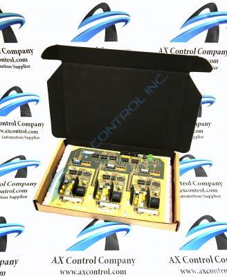
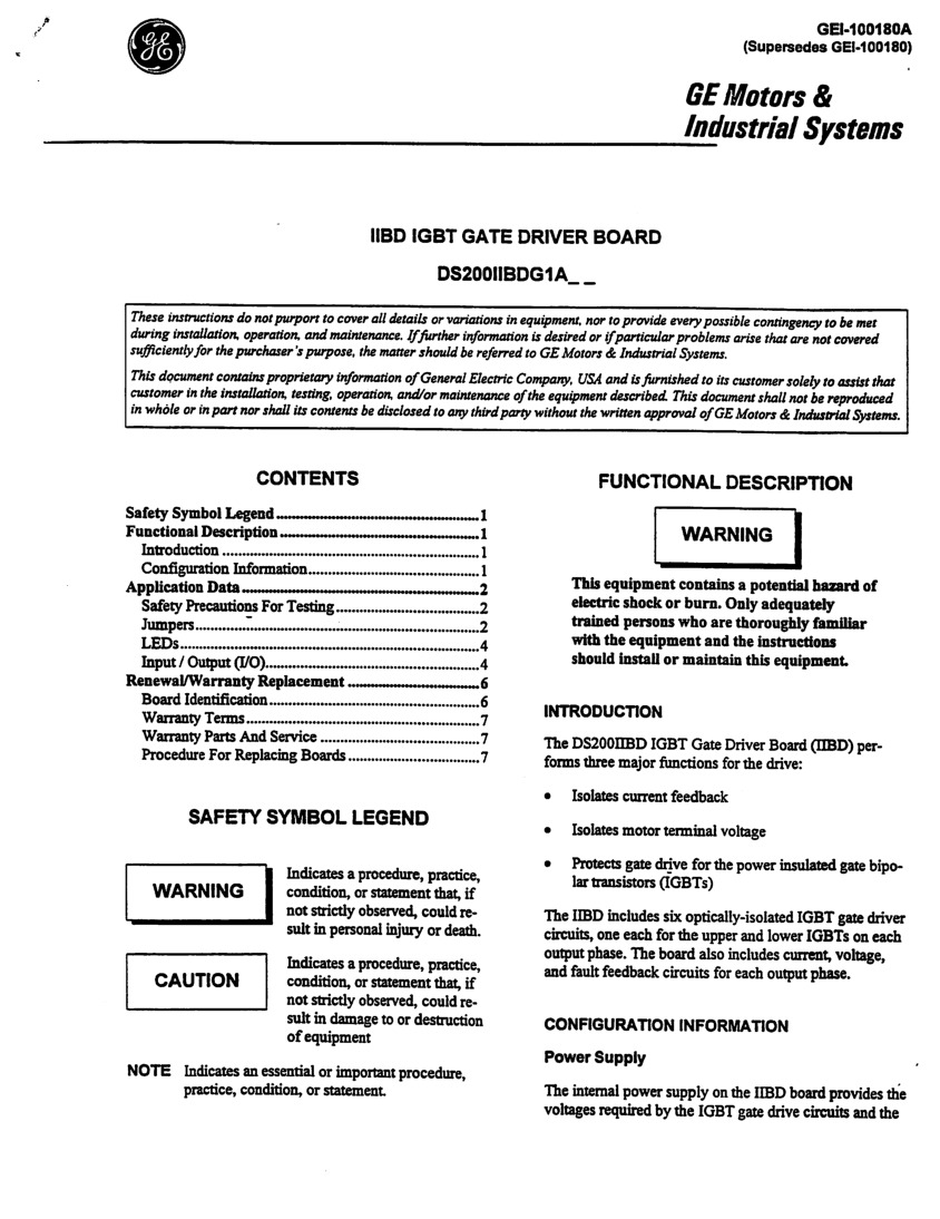
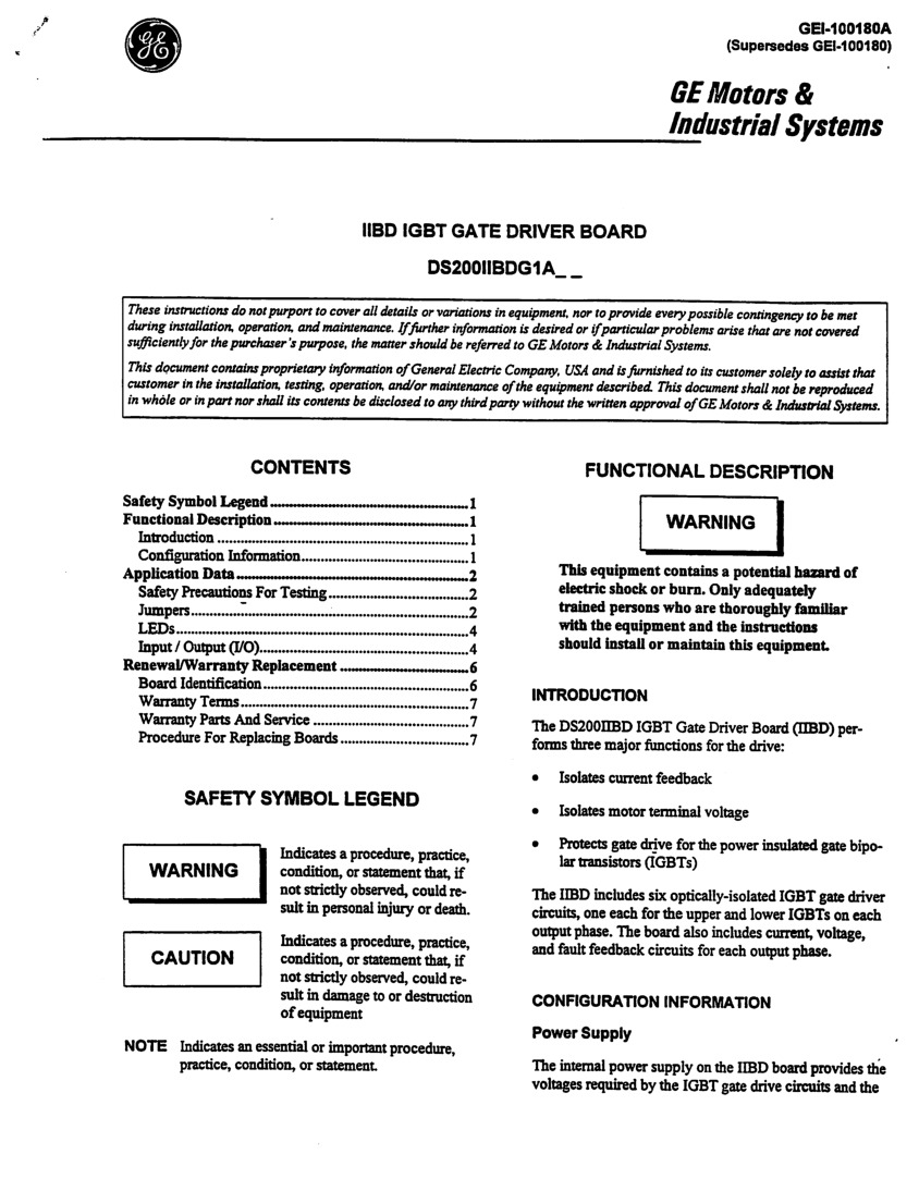
About the DS200IIBDG1AGA
This DS200IIBDG1AGA IGBT Gate Driver Board was originally designed for production within the Mark V Series of General Electric products. The Mark V Series is a continually-developed series of turbine control systems and turbine control system components that began with the Mark 1 in the late 1960s and has been maintained by the original manufacturer ever since. This DS200IIBDG1AGA IGBT Gate Driver Board is actually considered a legacy series product, as the Mark V Series that it belongs to is no longer being manufactured by General Electric, in lieu of newer product series. This DS200IIBDG1AGA IGBT Gate Driver Board is modified from its parent Mark V Series circuit board through the addition of a full range of three significant revisions; two functional product revisions and an artwork revision.
Hardware Tips and Specifications
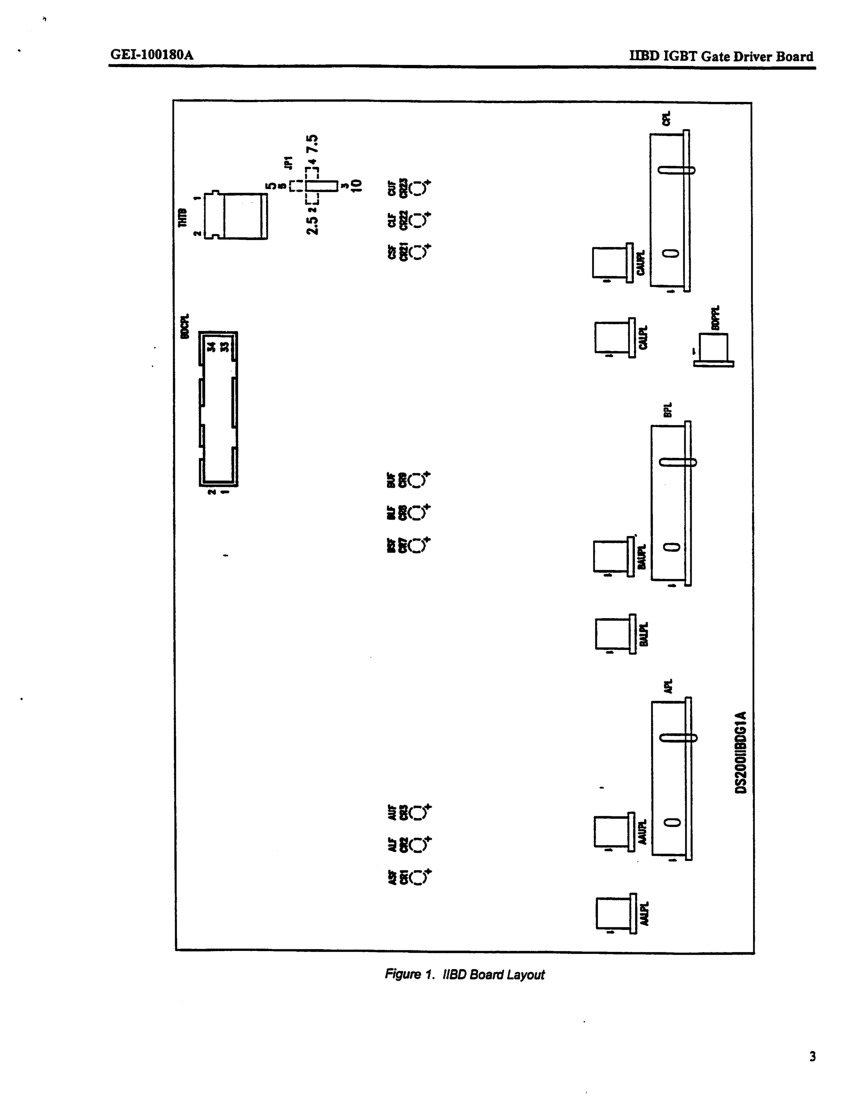
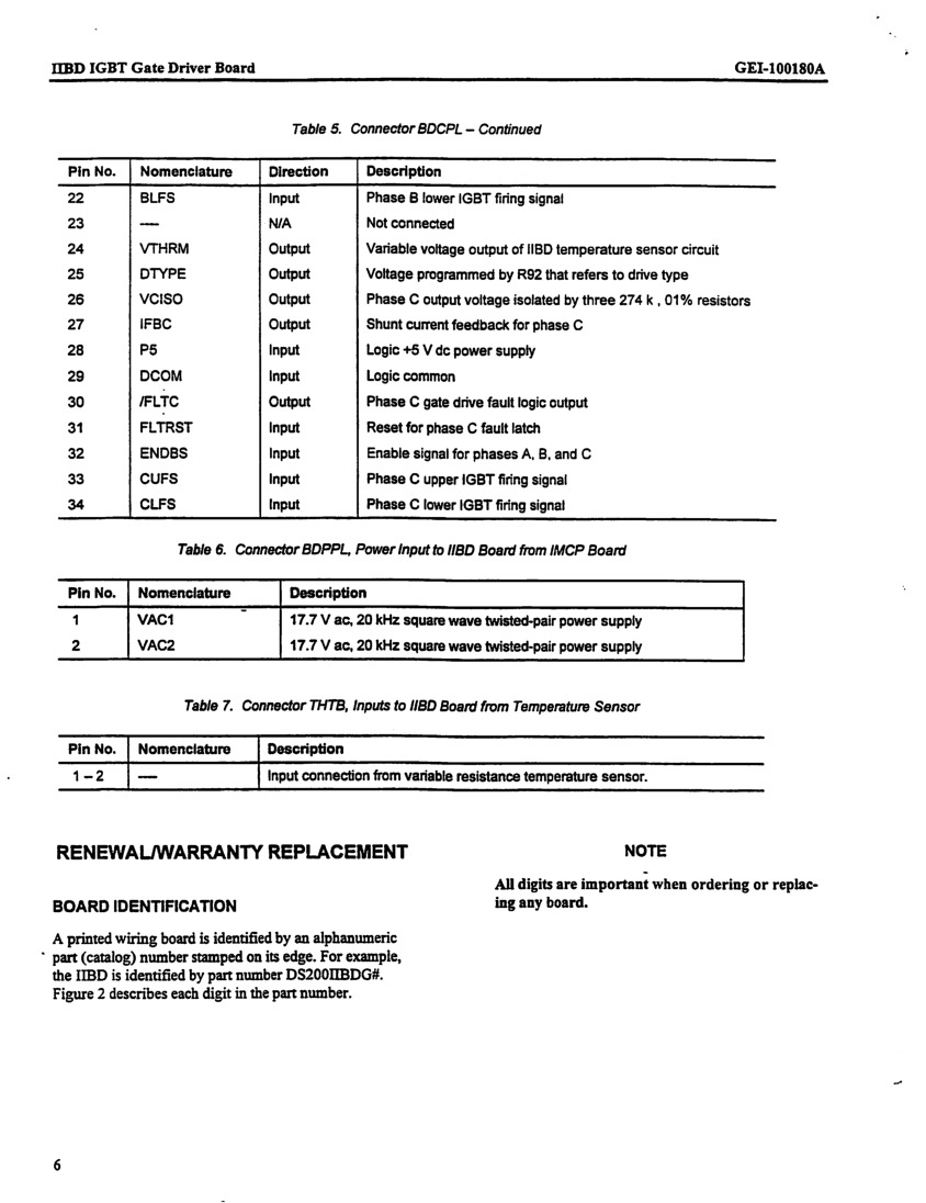
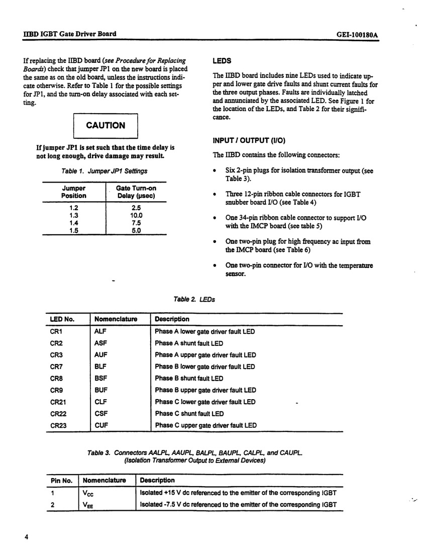
The GE Insulated Gate Bipolar Transistor (IGBT) Board DS200IIBDG1AGA contains nine indicator LEDs that provide a status of the processing. The LEDs are visible from the interior of the circuit board cabinet and are red in color when lit. The LEDs are located on the board in three groups and each group contains three LEDs. Each group of LEDs is associated with an 8-pin connector that is located adjacent to the LEDs. The LEDs indicate the status of the signal that is received or transmitted from the 8-pin connector. The three 8-pin connectors are identified as APL, BPL, and CPL on the GE Insulated Gate Bipolar Transistor (IGBT) Board DS200IIBDG1AGA. Also, the DS200IIBDG1AGA board featured here is populated with a 34-pin connector that is comprised of two rows of 17 pins, with a singular ribbon cable being able to connect to the 34-pin connector. This mentioned ribbon cable is connected also to a board in the cabinet and must be routed properly to avoid touching other components. The cabling is confined to the interior of the drive only.
To remove the defective DS200IIBDG1AGA board for replacement, you must remove six screws that hold the board in the structure inside the cabinet. When you use a screwdriver to remove the screws, make sure you do not brush against other components in the cabinet or the solder points on the boards. It is important to have a clear view of the components so you can avoid damage. Retrieve any screws that fall into the drive, to ensure normative functionality of the Mark V Series drive assembly. While this DS200IIBDG1AGA IGBT Gate Driver Board does have three total product revisions; it still possesses the normal assembly type standard to so many General Electric Speedtronic products.


