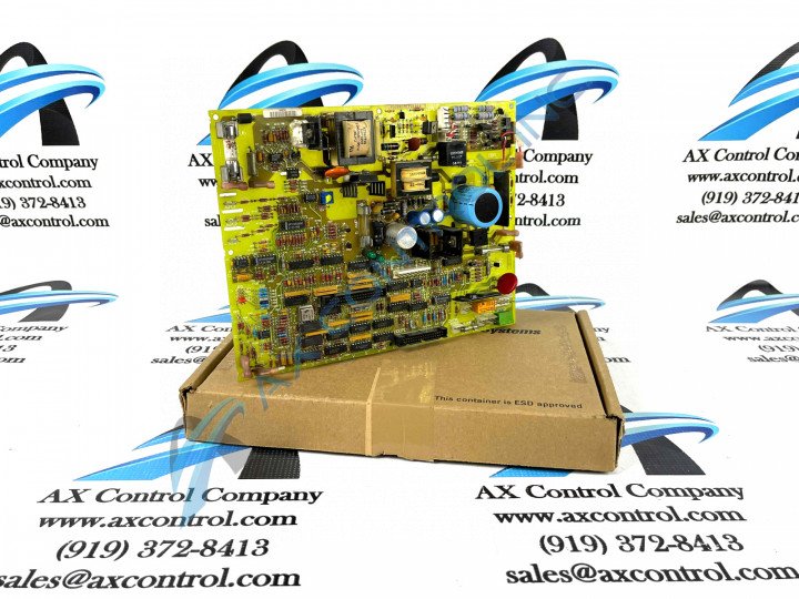
About the DS200IMCPG1ADA
This DS200IMCPG1ADA printed circuit board or PCB for short plays an important role in its greater Mark V Series as a Power Supply Interface Board, specifically. This IMCP-abbreviated product, as alluded to above, was originally manufactured for use in standard wind, gas, and steam turbine control and management system applications typical to the Mark V Series. The Mark V Series that this DS200IMCPG1ADA Power Supply Interface Board belongs to its considered a legacy series, as it has been discontinued for manufacture in the years since its original conception. While a legacy series, this DS200IMCPG1ADA PCB's Mark V Turbine Control System Series is one of the latest General Electric product series to make use of their patented Speedtronic technology, which was first introduced with the rollout of the Mark I in the later 1960s. While this DS200IMCPG1ADA PCB is certainly definable as a Power Supply Interface Board in its own right, it is not the original product of its specific functionality to exist within the Mark V Series; that would be the DS200IMCPG1 parent Power Supply Interface Board missing all three of this DS200IMCPG1ADA product's three significant product revisions.
Hardware Tips and Specifications
While not the most well-documented product offering from General Electric, this DS200IMCPG1ADA PCB is accompanied by a set of installation specifications, and offers a series of hardware elements available upon a visual inspection and DS200IMCPG1ADA functional product number breakdown. For starters, the assembly of this DS200IMCPG1ADA Mark V TUrbine Control System Series product seems to possess a standard number of normal Mark V Series voltage-limiting and storing hardware components, such as diodes, rectifiers, capacitors, and integrated circuits. This DS200IMCPG1ADA Power Supply Interface Board also seems to have been factory-drilled in numerous positions for installation purposes, with each factory-drilled installation hole being ringed with insulated material. The DS200IMCPG1ADA functional product number is an additional source of DS200IMCPG1ADA-specific hardware information, with individual naming elements coding for this DS200IMCPG1ADA PCB's:
- Normal Mark V Series assembly version
- Domestic location of original manufacture
- IMCP functional product acronym
- Normal style of PCB protective coating
- Group one Mark V Series grouping
- A-rated primary functional revision
- D-rated secondary functional revision
- A-rated artwork configuration revision
The GE IAC2000I Power Supply Interface Board DS200IMCPG1ADA can be connected through a cable to the DS200SDCC Drive Control Board; this process is detailed in original DS200IMCPG1ADA instructional manuals. To start, connect the cable to the 1PL connector on the Drive Control Board. Four screws secure the GE IAC2000I Power Supply Interface Board DS200IMCPG1ADA inside the board cabinet; have a screwdriver on hand when you start the replacement procedure and use it to remove the four screws. The screwdriver must not touch any components in the cabinet or scratch the surface of the other boards. Also, if a screw falls into the DS200IMCPG1ADA PCB's greater drive cabinet immediately retrieve it and keep all four screws together and in a safe place for use when you install the replacement. Before you unscrew the defective board and remove the cables, inspect the board and and note where the cables are connected. Note the connector numbers that identify the connectors and make labels to place on the cables that will help you know where the cables reconnect on the board. Pull the board out of the protective bag and smooth out the bag flat on a flat surface, before placing the DS200IMCPG1ADA board on top of the bag. The board also is populated with one jumper that you can configure for your purposes. Note how the jumper is set on the defective board and set the jumper to the identical position on the new board. The jumper in this DS200IMCPG1ADA PCB's assembly may only be used for testing purposes by the factory.


