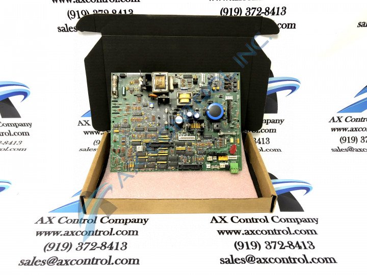
About the DS200IMCPG1CBA
This DS200IMCPG1CBA printed circuit board product offering from General Electric was, as briefly discussed above, originally designed and manufactured by General Electric, specifically for placement in their Mark V Turbine Control System Series. The Mark V Series that this DS200IMCPG1CBA PCB belongs to, as evidenced by its full extended series name, has a series of set applications in the control and management systems of popular and compatible wind, steam, and gas turbine automated drive assemblies, although it has to be considered obsolete as a whole, as it exists as a legacy product series discontinued for manufacture due to a retailer-identified functional series obsolescence in one of the many years past its initial General Electric Mark Series release. This DS200IMCPG1CBA Board's greater Mark V Series, while obsolete as a whole, still attracts its own cult demand on the greater figurative automated industrial marketplace, as it exists as one of the finally-developed GE Mark product series to incorporate the patented Speedtronic control system technology across a range of its different offerings.
Hardware Tips and Specifications
The GE IAC2000I Power Supply Interface Board DS200IMCPG1CBA can be connected through a cable to the DS200SDCC Drive Control Board. Connect the cable to the1PL connector on the Drive Control Board. The GE IAC2000I Power Supply Interface Board DS200IMCPG1CBA is populated with two green LEDs that provide you with a quick indiction of the health of the board. You can view the LEDs on the board by opening the cabinet door and locating the LEDs. For a more complete diagnostic inspection, use the diagnostic tools on the drive that are accessed from the drive control panel. This DS200IMCPG1CBA printed circuit board or PCB for short actually does not exist as the originally-developed product of its specific Mark V Series functionality; that would be the DS200IMCPG1 parent Power Supply Interface Board missing this DS200IMCPG1CBA device's three significant product revisions including two functional product revisions and an artwork configuration revision.
Ribbon cable connectors are also located on the board. One 34-pin connector and one 40-pin connector are available to carry control signals to the board or transmit signals from the board. The board is secured inside the board cabinet with four holes in the board. The holes in the board match the holes in the board rack. If you over tighten the screws you might cause the board to crack or break. So, it is important to only tighten the screws enough to secure the board. Also, use one hand to hold the screw and one hand to turn the screwdriver. In this way, the screw will not fall inside the drive cabinet. Keep the screws together in a safe place because they might otherwise get lost or scattered. Have a good view of the screwdriver when it is in the board cabinet to keep it from hitting components or causing other damage to the boards. Given this DS200IMCPG1CBA device's initial attribution to the Mark V Turbine Control System Legacy Series, it should not come as too much of a surprise that it is not surrounded by any great amount of pertinent original instructional manual information online. With this being the case, the DS200IMCPG1CBA functional product number itself can be considered a strong primary source of DS200IMCPG1CBA Board hardware component and component specification information; coding for specific details in a series of consecutive functional naming elements. For instance, the DS200IMCPG1CBA functional product number begins with the dual-functional DS200 series tag delegating this DS200IMCPG1CBA device's normal Mark V Series assembly as well as its domestic original manufacture location. Some of the other relevant hardware information revealed by way of this DS200IMCPG1CBA PCB's functional product number includes its:
- IMCP functional product abbreviation
- Group one Mark V Series product grouping
- Normal PCB coating style
- Full three-fold revision history


